![]()
CHAPTER 1
Crystal structure
Beauty when uncloth’d is clothè d best.—Phineas Fletcher (1582–1650)
1.1 INTRODUCTION
The aim of solid state physics is to explain the properties of solid materials as found on Earth. For almost all purposes the properties are expected to follow from Schrödinger’s equation for a collection of atomic nuclei and electrons interacting with electrostatic forces. The fundamental laws governing the behaviour of solids are therefore known and well tested. It is nowadays only in cosmology, astrophysics and high-energy physics that the fundamental laws are still in doubt.
In this book we shall be concerned almost entirely with crystalline solids, that is solids with an atomic structure based on a regular repeated pattern, a sort of three-dimensional wallpaper. Many important solids are crystalline in this sense, although this is not always manifest in the external form of the material. Because calculations are easier, more progress has been made in understanding the behaviour of crystalline than of non-crystalline materials. Many common solids—for example, glass, plastics, wood, bone—are not so highly ordered on an atomic scale and are therefore non-crystalline. Only recently has progress been made in understanding the behaviour of non-crystalline solids at a fundamental level.†
Even in the restricted field of crystalline solids the most remarkable thing is the great variety of qualitatively different behaviour that occurs. We have insulators, semiconductors, metals and superconductors—all obeying different macroscopic laws: an electric field causes an electric dipole moment in an insulator (Chapter 9), a steady current in a metal or semiconductor (Chapters 3 to 6) and a steadily accelerated current in a superconductor (Chapter 10). Solids may be transparent or opaque, hard or soft, brittle or ductile, magnetic or nonmagnetic.
In this chapter we first introduce in Section 1.2 the basic ideas of crystallography. In Section 1.3 we describe some important crystal structures and in Section 1.4 we explain how x-ray diffraction is used to determine crystal structure. In Section 1.5 we discuss quasi-crystals, ordered solids that challenge much of the conventional wisdom concerning crystalline materials. Section 1.6 contains a qualitative description of the interatomic forces responsible for binding atoms into solids.
1.2 ELEMENTARY CRYSTALLOGRAPHY
A basic knowledge of crystallography is essential for solid state physicists. They must know how to specify completely, concisely and unambiguously any crystal structure and they must be aware of the way that structures can be classified into different types according to the symmetries they possess; we shall see that the symmetry of a crystal can have a profound influence on its properties. Fortunately we will be concerned in this book only with solids with simple structures and we can therefore avoid the sophisticated group theoretical methods required to discuss crystal structures in general.
1.2.1 The crystal lattice
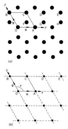
We will use a simple example to illustrate the methods and nomenclature used by crystallographers to describe the structure of crystals. Graphite is a crystalline form of carbon in which hexagonal arrays of atoms are situated on a series of equally spaced parallel planes. The arrangement of the atoms on one such plane is shown in Fig. 1.1(a). We choose graphite for our example because a single two-dimensional plane of atoms in this structure illustrates most of the concepts that we need to explain. Solid state physicists often resort to the device of considering a system of one or two dimensions when confronted with a new problem; the physics is often (but not always) the same as in three dimensions but the mathematics and understanding can be much easier.
To describe the structure of the two-dimensional graphite crystal it is necessary to establish a set of coordinate axes within the crystal. The origin can in principle be anywhere but it is usual to site it upon one of the atoms. Suppose we choose the atom labelled O in Fig. 1.1(a) for the origin. The next step is a very important one; we must proceed to identify all the positions within the crystal that are identical in all respects to the origin. To be identical it is necessary that an observer situated at the position should have exactly the same view in any direction as an observer situated at the origin. Clearly for this to be possible we must imagine that the two-dimensional crystal is infinite in extent. Readers should convince themselves that the atoms at A, B, C, D and E (and eight others in the diagram) are identical to the atom at the origin but that the atoms at F, G and H are not; compare for example the directions of the three nearest neighbours of the atom at O with the directions of the three nearest neighbours of the atom at F. The set of identical points identified in this way is shown in Fig. 1.1(b) and is called the crystal lattice; comparison of Figs. 1.1(a) and (b) illustrates clearly that the lattice is not in general the same as the structure. Readers should convince themselves that, apart from an unimportant shift in position, the lattice is independent of the choice of origin. Having identified the crystal lattice in this way the coordinate axes are simply obtained by joining the lattice point at the origin to two of its neighbours.
Fig. 1.1 Two-dimensional crystal of carbon atoms in graphite: (a) shows how the atoms are situated at the corners of regular hexagons; (b) shows the crystal lattice obtained by identifying all the atoms in (a) that are in identical positions to that at O. The crystal axes, lattice vectors and conventional unit cell are shown in both figures
There are many ways of doing this but the conventional choice for graphite is to take OA and OB for the x and y axes as shown in Fig. 1.1(b). Note that the coordinate axes for graphite are not orthogonal. An example of an unconventional choice of coordinate axes for graphite would be to take OA for the x axis as before but to take the OD direction for the y axis. The distances and directions of the nearest lattice points along the x and y axes are specified by the lattice vectors a and b respectively (Fig. 1.1.(b)). The crystal lattice is completely defined by giving the lengths of a and b and the angle γ between them. For graphite we have a = b = 2.46 Å, γ = 120° (1 Å = 1 ångstrom = 10−10 m). The conventional choice of axes for graphite therefore clearly reflects the hexagonal symmetry of the structure; this is not the case for the unconventional choice discussed above.
The positions of all the lattice points of the two-dimensional graphite crystal are reached by drawing all possible vectors of the form
from the origin, where u and υ take on all possible integer values, positive, negative and zero. That the crystal appears identical when viewed from all the positions given by this equation is an indication that it possesses the important property of translational invariance.
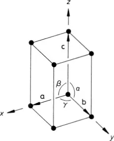
The generalization of the above ideas to a three-dimensional crystal is straightforward. An origin is chosen and all the points within the crystal that are identical to it are identified; this set of points constitutes the three-dimensional crystal lattice. The directions of the crystal coordinate axes are then defined by joining the lattice point at the origin to three of its near neighbours (Fig. 1.2). The choice of neighbours is sometimes obvious but, where this is not the case, convention usually dictates the choice that most clearly reflects the symmetry of the lattice. The distances and directions of the nearest lattice points along the crystallographic x, y and z axes are specified by the three lattice vectors a, b and c. The lattice is completely specified by giving the lengths of a, b and c, and the angles α, β, and γ between them (Fig. 1.2). The positions of all the lattice points are reached by drawing all possible vectors of the form
Fig. 1.2 Crystallographic axes and unit cell for a three-dimensional crystal lattice
from the origin. The ability to express the positions of the points in this way, with a suitabl...