Technology & Engineering
Fatigue Crack Initiation
Fatigue crack initiation refers to the process by which cracks begin to form in a material due to repeated cyclic loading. This phenomenon is a common cause of failure in engineering structures and components, particularly in materials subjected to dynamic stress. Understanding and managing fatigue crack initiation is crucial for ensuring the reliability and safety of various mechanical systems.
Written by Perlego with AI-assistance
Related key terms
1 of 5
11 Key excerpts on "Fatigue Crack Initiation"
 eBook - ePub
Fatigue of Materials and Structures
Fundamentals
- Claude Bathias, André Pineau, Claude Bathias, André Pineau(Authors)
- 2013(Publication Date)
- Wiley-ISTE(Publisher)
Chapter 3Fatigue Crack Initiation 1
3.1. Introduction
If we want to accurately estimate the fatigue behavior of mechanical parts we have to evaluate the number of cycles that occur before crack initiation within a region which is highly stressed or containing fabrication defects. In many practical cases, the initiation stage represents a significant part of the fatigue life (by up to 90% of the lifetime), as is highlighted in Chapter 4 .Experience shows us that crack initiation usually results from the concentration of plastic deformations that occur within a small region of finite dimension. From a structural point of view, localized plastic deformations related to extrusion and intrusion mechanisms lead to the development of stage I cracking.From a practical point of view, we have to relate the number of cycles necessary for the formation of a macroscopic initiation event to the operating conditions (applied loads, design of the components) in order to calculate the total number of cycles to failure.This chapter examines the two sides of the problem: physical mechanisms and methods of evaluating the number of cycles for crack initiation.3.2. Physical mechanisms of crack initiation
3.2.1. Three stages of fatigue failure: a reminder
When a specimen or a component fails due to fatigue, its life can be split into three parts: – crack initiation; – slow crack propagation; – sudden propagation leading to fracture.3.2.1.1. Definition of crack initiationThe definition of crack initiation can be different depending on whether we focus on the microstructural evolution of the material or the formation of a microcrack. We will come back to this definition in Chapter 4 .To evaluate the crack initiation stage within a structure, we usually rely on the notion of microcracking. This notion itself, however, depends directly on the resolution of the means of observation used. Moreover, as there is no general agreement on the definition of crack initiation, different authors have defined the number of cycles to crack initiation,Ni eBook - PDF
Random Fatigue
From Data to Theory
- K. Sobczyk, B. F. Spencer Jr., B. F. Spencer, Jr.(Authors)
- 2012(Publication Date)
- Academic Press(Publisher)
Chapter I Fatigue of Engineering Materials: Empirical Background 1. Introductory Remarks In general, fatigue can be defined as a phenomenon that takes place in com-ponents and structures subjected to time-varying external loadings and that manifests itself in the deterioration of the material's ability to carry the in-tended loading. The fatigue phenomenon today is deemed to originate in the local yield of the material or, in other words, in the sliding of atomic layers. This slid-ing is caused by a combination of dislocations and local stress concentra-tions. It is assumed that each slip, no matter how small, is connected with a small deterioration of the material structure. Under cyclic stress conditions, there is migration of dislocations that result in localized plastic deforma-tions. Microscopic cracks are created that grow and join together to pro-duce major cracks. Nucleation (or crack initiation) and crack growth are commonly regarded as basic causes of fatigue damage accumulation and ultimate fatigue failure. Nucleation and crack growth also constitute two principal phases in the fatigue damage process. (See Fig. 1.1.) The fatigue crack nucleation process is not yet fully understood; how-ever, several models have been proposed to explain the origin of fatigue cracks. (See [23], [36].) In these models, various dislocation mechanisms in the metallic structure play a dominant role. Usually, fatigue cracks occur on the free surface of the body at places of high stress concentration (e.g., inclusions, surface imperfections, grain boundaries, etc.). Depending upon the material properties and the applied loading, the nucleation phase can be 9 10 /. Fatigue of Engineering Materials: Empirical Background complete lifetime nucleation micro-crack growth -10Ä — — , -nucleation period macro-crack growth final failure lmm-crack growth period Figure 1.1. Fatigue life of a structural element. of a different importance in estimating fatigue life. eBook - PDF
- Vladimir V. Bolotin(Author)
- 2020(Publication Date)
- CRC Press(Publisher)
Chapter 2 FATIGUE CRACK NUCLEATION AND EARLY GROWTH 2.1 Introductory Remarks The aim of this chapter is to discuss analytical models for the prediction of fatigue crack nucleation and early growth. The preliminary stage frequently takes a signif- icant portion of the total fatigue life. Moreover, even now, when the fail-safe and damage-tolerant concepts are widely spread in engineering applications, the forma- tion of a macroscopic crack, e.g., a visible one, is sometimes considered as a kind of failure after which the structural component must be withdrawn out of operation. Putting apart structural safety considerations, one must state that the theory of crack nucleation and early growth enters, as an essential part, into the theory of fatigue. In particular, if a crack is born in a "natural" way, final conditions of the first stage become initial conditions for the stage of regular fatigue crack growth. We do not mention that some models used in the theory of fatigue crack nucleation intrinsically enter into the theory of fatigue crack propagation. The problem of Fatigue Crack Initiation and early growth may be referred to both micro- and macromechanics of fracture (see Section 1.5). In general, the bor- der between micro- and macrocracks is rather vague. From the practical viewpoint, it is expedient to draw such a border, taking into account detectability of cracks with common nondestructive inspection techniques. Then the border depends on the current state of these techniques. It depends also on the scale of the material's microstructure. For example, the detectable size of cracks in aircraft engineering is of the order 1 mm, and those in large concrete structures may be much larger, say, of the order 10 mm. In addition, the distinction between micro- and macro- cracks is complicated by the problem of so-called "short," "physically small" or just "small" cracks. eBook - PDF
- Arun Shukla(Author)
- 2004(Publication Date)
- CRC Press(Publisher)
CRACK PROPAGATION Before entering the regime of crack propagation it is well to summarize some of the characteristics of the crack initiation process. F IGURE 5.15 Tensile strength vs. strain hardening ( n , strain hardening exponent; S u , tensile strength; S y , yield strength). Crack Mechanics 171 The initiation of cracks can only take place in the regions of plastic defor-mation. As long as the strains are elastic, even in the face of geometrical discon-tinuities and residual stresses, fatigue cracks do not start. In the great majority of structures we find fields of nominal elastic stresses surrounding the localized, plastically deformed pockets of material. Under cyclic loading these pockets can be transformed into nuclei for Fatigue Crack Initiation. Such pockets of plasticity are caused by strain raisers embedded in the elastic field. The transition from a plastic region to an elastic field is strongly affected by the size of the notch (or crack) and the size of the plastic zone in relation to the size of the specimen. Contrary to general intuition, cracks can also be initiated under compres-sive cycling loading. However, they can only propagate through the plastically deformed region. On the other hand, cracks initiated under tensile – cycling load-ing will propagate beyond the plastically deformed region to cause a fracture of the test specimen. We normally deal with two crack realities. These are preexisting flaws and the cracks that gradually develop during the service life of the structure. The non-destructive techniques and proof-testing procedures tend to identify the upper limits of the cracks and establish the minimum fatigue life criteria for specific structural components. The prediction of a service life, in turn, depends on the degree of understanding of the rate of fatigue crack growth. The general principle of this phenomenon is briefly illustrated in Fig.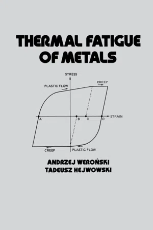 eBook - PDF
- Andrzej Weronski(Author)
- 1991(Publication Date)
- CRC Press(Publisher)
1 Mechanical Fatigue 1.1 INTRODUCTION The commonly accepted definition of mechanical fatigue is that it is a complex of phenomena caused by progressive, cumulatively increasing damage to material accumulated in each of successive loading cycles. It is noteworthy that fracture is produced by stresses that are only a fraction of the static strength and that the number of loading cycles encountered in service by an element can be as high as 108. Some authorities maintain that about 80 to 90% of all failures ending in fracture are connected with fatigue. Fatigue failure caused by material imperfections is rather rare; the majority of accidents have, as a sole or contributory cause, a design or maintenance fault. Since Wohler’s investigation of the causes of a series of catastrophic failures to railway axles, summarized in his 1870 article, scores of thousands of publications devoted to mechanical fatigue have been published, but the knowledge gathered has been neither cohesive nor comprehensive. Furthermore, it seems unrealistic to reach a converse opinion when considering the variety of factors that influence the fatigue life and the difficulties in describing the state of real solid matter. Mechanical fatigue is a particular case of thermal fatigue. Both have the same source of damage: repeatedly applied stresses of different origin, caused by either external load or temperature transients. This intuitively deducted identity is only sometimes found to be valid; its particular aspects are discussed later. In many situations encountered in industry, a device such as a forging die is loaded simul-taneously by external forces and thermal stresses. Moreover, to discuss thermal fatigue it is convenient to accept the descriptive methods developed in earlier studies.
- H. Liebowitz(Author)
- 2014(Publication Date)
- Academic Press(Publisher)
VI. Recommended Research Since the review of a field that is important but in which nevertheless exists little research is necessarily interwoven with recommended research/' it may seem necessary to repeat or summarize such recommen-dations. The nature of the fatigue process in high-strength materials should be studied by methods successfully applied to pure metals, while also trying new techniques to reveal the more localized events and to overcome the overshadowing effect of precipitates. The effect of continuously varying amplitudes should be studied first in pure metals and subsequently in complex alloys. Although fatigue is a highly localized phenomenon, it is still important to study the mechanism of overall deformation in the cyclic state. Attempts should be made to observe local changes in the microstructure and dislocation structure during the period of fatigue life spent in the cyclic state where there seems to be no change in bulk properties and energy dissipation. Crack-propagation experiments should reproduce the natural fatigue phenomenon starting from less severe notches. Eddy-current crack detectors are recommended for determining crack dimensions. A model for a quantitative theory of crack propagation should be based on the energy balance at the crack tip, in which it is attempted to establish the values for the various energy components by analytical or experimental methods. Observations in the highly localized regions of the crack tip are necessary. These observations should be concerned with the size of the plastically deformed zone at the crack tip, the existence of local (crack tip) strain hardening or softening, and the interaction of the crack with the dislocation structure of the cyclic state (precrack state). More detailed studies of the mechanism of crack propagation and crack morphology, reported in previous sections, could help in approaching an estimate of the various amounts of strain work eBook - PDF
Fracture Mechanics
Worked Examples
- John Knott, Paul Witney(Authors)
- 2019(Publication Date)
- CRC Press(Publisher)
S. Fatigue Crack Growth If a material is subjected to a cyclic stress which is well below the yield strength mechanical failure would not generally be expected. However, if there is a feature in the component such as a crack, an indusion or a sharp geometrical discontinuity the stress may be raised locally 10 a level greater than the yield strength and crack initiation and growth may occur. As the applied stresses are cycled the crack may extend by a small amount on each cycle. This is known as fatigue crack growth. 5.1 The Paris-Erdogan Equation The graph of fatigue crack length versus number of cycles usually has the form shown in figure 5.1 dLJ/dN == gradient Number of Cycles, N Figure 5.1 The graph may be used to calculate how fast a crack is growing al any particular point by measuring the gradient of the curve at the point of inleresl. This measure is the crack-growth-increment per cycle. drJ/dN, and its derivation is demonstrated in figure 5.1. For quasi-elastic (LEFM) conditions. the most popular, empirical relationship between the crack-growth-increment per cycle (da/dN) and parameters of stress range (.1.0) and the instantaneous crack length (a) is that proposed initially by Paris and Erdogan which gives: 86 S. Fatigue Crack Growth If a material is subjected to a cyclic stress which is well below the yield strength mechani cal failure would not generally be expected. However, if there is a feature in the component such as a crack, an indusion or a sharp geometrical discontinuity the stress may be raised locally 10 a l evel greater than the yield strength and crack initiation and growth may occur. As the applied stresses are cycled the crack may extend by a small amount on each cycle. eBook - PDF
Fatigue Crack Propagation in Metals and Alloys
Microstructural Aspects and Modelling Concepts
- Ulrich Krupp(Author)
- 2007(Publication Date)
- Wiley-VCH(Publisher)
By the time-de- pendent mechanisms mentioned above, however, the crack can grow to a critical crack length of a crit , which is required to overcome the barrier. Then, fatigue-crack propagation may resume, and, consequently, the fatigue limit disappears. In the Wöhler diagram (S/N curve) this would correspond to a continuously decreasing stress value. This modified analysis of the fatigue limit manifests the technical importance of a detailed understanding of the fundamental mechanisms leading to technical crack initiation. Together with the discussion on crack propagation mechanisms in Chapter 6, the main microstructural parameters are reviewed and at least qualita- tively evaluated in order to provide a sound basis for mechanism-based modeling approaches, which are introduced in Chapter 7 and which are going to serve as im- portant tools for future development and evaluation of fatigue-resistant materials and new methods of service-life prediction. 128 5 Initiation of Microcracks Fig. 5.22 Two-stage S/N diagram (Wöhler diagram) covering also the VHCF regime. Fig. 5.23 Elimination of the fatigue limit by superimposition of time-dependent damage pro- cesses: schematic representa- tion of the crack propagation rate da/dN vs. the crack length a (according to [287, 288]). 5.6 Crack Initiation in Inhomogeneous Materials: Cellular Metals The previous remarks on crack initiation in this chapter were restricted to metals and alloys that can be considered as homogeneous, except for variation of crystal- lographic orientation and the presence of secondary phases. The latest technical developments require more and more materials that fulfill special functionalities or low weight restrictions. Hence, materials research moves considerably to “mod- ern” material concepts, e.g., composite materials, smart materials or cellular mate- rials. All these structures show special kinds of damage mechanisms, which often have to be discussed on the basis of different length scales.
- Wole Soboyejo(Author)
- 2002(Publication Date)
- CRC Press(Publisher)
S in ce th en , a great deal o f research h as b een carried o u t to in vestigate variou s asp ects o f fatigu e. A su m m ary o f the results o b ta in ed from w ell-estab lish ed prior research on the fatigu e o f m aterials is p resen ted in this chapter. 460 Chapter 14 14.2 MICROMECHANISMS OF Fatigue Crack Initiation M icro cra ck s ten d to in itia te in reg io n s o f h igh stress co n c en tra tio n su ch as th o se a ro u n d n o tc h e s a n d in clu sio n s. T h ey m a y a lso in itia te in th e cen tral reg io n s o f grain s, or in th e grain b o u n d a ries, ev en w h en n o m a c ro sc o p ic stress raisers are p resen t. In gen eral, h o w ev er, m icro cra ck s in itia te as a result o f slip p ro cesses (W o o d , 1958) d u e to stress or p la stic strain cyclin g. D islo c a tio n s eith er em erge at the su rface or p ile u p a g a in st o b sta cle s su ch as grain b ou n d a ries, in c lu sio n s, an d o x id e film s, to form slip b a n d s, w h ich w ere first o b serv ed b y E w in g an d H u m frey (1903). T h o m p so n et al. (19 5 6 ) later sh o w e d th a t if th ese slip b a n d s are rem o v ed b y e le ctr o p o lish in g , th ey w ill reap p ear w h en fa tig u in g is reco m m en ced , an d so th ey referred to th em as p ersisten t slip b an d s (P S B s). T h e resistan ce to the in itia tio n o f slip at the cen tral p o r tio n d ecreases w ith in creasin g grain size, fo llo w in g th e H a ll-P e tc h rela tio n (H a ll, 1951; P etch , 1953). T h e resistan ce o f the grain b o u n d a ry reg io n s can a lso be w ea k en ed in so ft p recip itate free z o n e s (P F Z s) (M u lv ih ill an d B eevers, 1986) at th e region s o f in tersectio n o f grain b o u n d a ries, e.g ., trip le p o in ts (M iller, 1987), by em b rittlem en t d u e to grain b o u n d a ry seg reg a tio n (L e w a n d o w sk i et al., 1987), an d a lso b y stress c o rr o sio n effects (C o ttis, 1986). eBook - PDF
- J. Edward Pope(Author)
- 1996(Publication Date)
- Gulf Professional Publishing(Publisher)
This approach should not be used with metals, because they undergo subcritical crack growth. Fatigue 349 FATIGUE TESTING Fatigue testing can be difficult and can yield misleading data if not done correctly. Numerous small companies spe- cialize in generating fatigue data, and their services might be useful to those without proper facilities or experience. Companies that decide to generate their own fatigue data should carefully review the pertinent ASTM guidelines: 1. Low Cycle Fatigue (ASTM Standard E606-80). 2. High Cycle Fatigue (ASTM Standard E466-82). 3. Statistical Analysis of Linear or LineadzeA Stress-Life and Strain-Life Fatigue Data (ASTM Standard E739-91) 4. Plane-Strain Fracture Toughness Test Method (ASTM Standard E399-90). 5. Fatigue Crack Growth and Threshold Crack Growth Test Method(ASTM Standard E647-91). 6. Creep Crack Growth Test Method (ASTM Standard E1457-92). 7. Surface Fatigue Crack Growth Test Method (ASTM Standard E740-88). ~ , Bhn 120 laO 200 240 280 320 300 400 440 480 520 t.o 'I I I l ~,t 'I ' i I ! ! 1 ~,,,,~~;, 9 ~ 11.7 8 ~ 0.2 ~ %b F7 --I I I ~ ~oo. 12o 14o leo mo ~ 22o 24o 2eo Figure 30. Surface factors for various machining opera- tions [13]. (R~rrted ~ t~vrnission of Pren~ce-Han, Inc.) It is particularly important to exercise care when testing to determine AKth. High loads are required to initiate a crack for testing purposes. If these loads are not reduced gradu- ally after initiation but before taking measurements to de- termine AK~, the tests may show the threshold value to be much higher than it actually is. Obviously, this could have very serious consequences. Every effort should be made to keep the test specimens as similar to the actual hardware as possible. Seemingly unimportant details, such as how a surface is machined, may induce residual stresses or create small cracks which dras- tically alter the fatigue life. Figure 30 shows how the sur- face factor (Cf) is related to tensile strength and machining operations [ 12].
- David C. Cranmer, David W. Richerson(Authors)
- 1998(Publication Date)
- CRC Press(Publisher)
Another technically important area is the use of high strength Si 3 N 4 at high temperatures where several strength degrading mechanisms may op erate simultaneously. The methods described below have proven useful in separating and characterizing the various mechanisms, and in providing the necessary input data for predictive models [56]. The types of fatigue and slow crack growth tests that are described in this chapter are grouped into one of two classifications by the authors: ( 1 ) fatigue crack propagation testing with short cracks, and ( 2 ) fatigue crack propagation with long cracks. There is not a universally definable crack length that is a threshold between short and long cracks; however, qualita tively they may be separated into the two classifications as described by the following. The classification of fatigue crack propagation testing with short cracks is comprised of those test specimens and techniques that are used to measure strength and its reduction as a consequence of fatigue. The effects of natural and artificial flaws (defined here as “ short” cracks) on the fatigue performance of structural ceramics are sought. The classification of fatigue crack propagation testing with long cracks is comprised of those test spec imens and techniques that are recognized as “ fracture-mechanics-type” specimens, that have inherently long cracks. This specimen geometry is typ ically used for fracture toughness measurements of structural ceramics. The long cracks in these “ fracture-mechanics-type” specimens are typically on the scale of millimeter-long lengths, while the short cracks (natural and artificial flaws) are on the scale of micrometers-up to hundreds of microm eter-long lengths.
Index pages curate the most relevant extracts from our library of academic textbooks. They’ve been created using an in-house natural language model (NLM), each adding context and meaning to key research topics.