![]()
CHAPTER 1
INTRODUCTION
CONTENTS
1.1 Introduction
1.2 Three-Phase Reactor
1.3 Application of a Gas-Interacting Slurry Reactor
1.4 Some Other Important Three-Phase Applications
1.5 Advantages of a Gas-Interacting Slurry Reactor
1.6 Challenges of a Gas-Interacting Slurry Reactor
Keywords
References
1.1 INTRODUCTION
A gas-interacting slurry reactor as a three-phase contactor is common in various chemical and biochemical processes. The slurry reactor are adapting in industry in various forms as per specific need of process. In this chapter, general features of the slurry reactor and its applications, advantage and disadvantage and their hydrodynamic behaviours are briefed. The gas-interacting downflow slurry reactor is one of the advanced reactors where contact time of the gas can be increased. The process description of the gas-interacting downflow slurry reactor on which the book is mainly focused is also described in this chapter.
1.2 THREE-PHASE REACTOR
The three-phase reactor is a multiphase contactor, where gas is distributed in a liquid in the presence of solid, which is used in various chemical and biochemical processes. The reactors can be designed either in for semibatch or continuous-mode operation. The gas comes in contact with the liquid and diffuses into the liquid from the surface of the gas bubble. The diffused gas is then transferred from the liquid to the solid surface, where then the reaction takes place. They are very common in the chemical, petroleum, food, mining, pharmaceutical and semiconductor industries for the specific application, where gas is reacted with the liquid in the presence of catalyst particle.
1.2.1 TAXONOMY OF GAS–LIQUID–SOLID SLURRY REACTOR
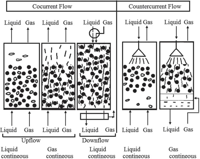
Various chemical processes in gas–liquid–solid reactors are carried out based on the flow patterns of the slurry. It can be broadly split into concurrent and countercurrent flows based on the direction of the gas and slurry flows (Epstein, 1981). Taxonomy of the flow operation is shown in Figure 1.1.
Cocurrent flow: In cocurrent flow, contacting modes are upflow and downflow, which characterize different hydrodynamic characteristics between solid particles and the enclosing gas and liquid as shown in Figure 1.2.
FIGURE 1.1 Taxonomy of three-phase flow.
FIGURE 1.2 Modes of gas–liquid–solid operation
Cocurrent upflow: The concurrent upflow modes are operated with two ways. One is called liquid-supported solid operation, while the other one is called bubble-supported solid operation. In case of liquid-supported solid operation, the liquid is in a continuous phase, where the solids are supported by the liquid with the dispersed gas bubbles. Epstein (1981) reported that the liquid-supported solids operation is governed at a minimum liquid velocity relative to solid terminal velocity. Different flow patterns such as coalesced bubble flow, dispersed bubble flow and slug flow are observed depending on the flow rate of the gas and liquid or slurry (Anderson and Quinn, 1970). In case of bubble-supported solids operation, the operation is characterized with the liquid velocity below the terminal velocity of solid or with the stationary liquid state in liquid batch. An increase in the gas flow rate in liquid-supported solid operation increases the formation of slug and decreases the liquid hold-up in the liquid–solid suspension. After an increase in the gas flow rate, the slurry forms segregated agglomerates and consequently bubble-supported operation prevails, in which the gas flows continuously and the liquid flows as a discrete phase either in as a flow of thin liquid films or as a liquid droplets (Mukherjee et al., 1974).
Cocurrent downflow: In this flow, the gas and liquid–solid mixture flow downward. The gas is distributed by specially designed distributor. The gas can be distributed in the column by liquid jet through an ejector (Sivaiah and Majumder, 2012). The jet is used to plunge on the fluid surface in the slurry medium in a column. During plunging, the gas is entrained by breaking the fluid surface and carries the gas downward as a dispersed phase of bubble. In the gas distribution zone, the bubbles are highly interacting with each other and continuously change their shape and size. The breakup of bubbles results in the formation of smaller bubbles and they are dragged downward by liquid momentum against their buoyancy. At high momentum (jet velocity > 15 m/s), the elongated bubbles are instantly formed, which may be referred as a slug flow condition. At this condition, the plunging zone increases by diminishing the bubbly zone (Majumder, 2016). In this regard, it is worth to include the invention of Shimodaira et al. (1981), which reports on biological treatment of waste water using a carrier floatable on water, and more particularly to a novel process for treatment of waste water utilizing a fluidized bed, which is formed by supplying waste water in a downflow operation. They claimed that the process is applicable to both anaerobic and aerobic biological treatment. The gas distribution without ejector system in case of downward flow may also result in annular, intermittent, separated, and dispersed flow patterns with only minor modifications (Crawford et al., 1986).
Countercurrent flow: This mode of operation is persuaded with liquid and gas, both as the continuous phases. The countercurrent gas-aided slurry reactor with continuous liquid phase is called inverse three-phase fluidization, whereas the reactor operated with continuous gas is called as a turbulent contact slurry bed reactor. In such cases, low-density solids relative to liquid is fluidized in a downflow contactor, by balancing the terminal velocity of the solid. The gas is flowed countercurrently to the liquid. Different flow regimes such as fixed bed with dispersed bubble, bubbling, transition, and slugging regime are observed in this operation (Fan et al., 1982a,b). In case of operation with continuous gas phase, a bed of low-density particles moves upward by the upward flow of gas continuously. At turbulent condition, the vigorous movement of particles results in tremendous gas–liquid contacting in the slurry column reactor. The taxonomy of the gas-interacting slurry reactor relates to the size of the reactor, methods of phase distribution and the reactor’s internals.
1.2.2 GAS-INTERACTING SLURRY REACTOR
A gas-interacting slurry reactor is defined as a three-phase bubble column reactor utilizing the catalyst as a fine solids suspension in a liquid. It is used to carry out reactions between gas made up of one or several reactive components and liquid in the presence of catalyst particles. The reactors are a simple cylindrical vessel with gas distributor at bottom or top. The liquid phase may be supplied in batch or it may move with or against the flow of the gas. If the reactions are highly exothermic, an internal heat exchanger is to be used in the reaction zone. Except for the presence of solids, this type of slurry reactor is identical to the bubble column reactor commonly used for gas–liquid contacting accompanied by the chemical reaction. In the condition where the gas solubility is low (liquid-phase mass transfer is important) and a large liquid hold-up is required, this type of reactor is ideal. In contrast to physical mass transfer operations, counter flow offers no significant advantages as the reaction itself ensures a sufficient concentration drop during the material exchange. The top of the bubble column is often widened to facilitate gas separation. The bubble column reactor is characterized by lack of any mechanical means of agitation; hence, gas is distributed more evenly in the liquid phase. The gas-aided slurry reactors offer several advantages in comparison to other kinds of multiphase reactors. They are subjected to an increasing use in industrial applications in various chemical and biochemical processes such as coal liquefactions, absorption, desorption and hydrocarbon synthesis. When compared to other conventional multiphase reactors (where solids are not moving with liquid or gas), the gas-interacting slurry reactors have several advantages through higher rate of heat and mass transfer, high selectivity and conversion per pass, less maintenance cost due to their easy procurement, the absence of moving parts, higher gas hold-up and producing more interfacial area and higher dispersion efficiency. According to industrial practice, such reactors are modified in suitable forms. The different types of modified ...