- 232 pages
- English
- ePUB (mobile friendly)
- Available on iOS & Android
eBook - ePub
An Introduction to Video and Audio Measurement
About this book
What do we measure and why? Peter Hodges explains the answer to this question in approachable language and with clear illustrations. Newcomers to the video industry, as well as those already established, will find this uniquely readable guide to the basics of a complex subject. Building on the success of the two previous editions of this popular title and covering both analog and digital video, the third edition includes new sections on audio measurement, high definition video, and innovative techniques of test and measurement.
Trusted by 375,005 students
Access to over 1 million titles for a fair monthly price.
Study more efficiently using our study tools.
Information
Subtopic
Communication StudiesPart One The Foundation
Chapter 1 Circuits and Signals
DOI: 10.4324/9780080575155-1
An electric signal is the sending of information by means of an electric circuit. Signals may take a variety of forms, they can be simple or complex, descriptions which change over time as technology develops. Today, audio may be described as a simple signal, yet where it is adapted to fit into, say, a mini-disc player it assumes a complexity far beyond that transmitted into our homes in the early days of wireless.
Video is a complex signal. In whatever form, video will always be complex. It must not only describe the picture but how it is constructed. To understand the video signal, we must go back to the beginning and look at the way a picture is converted into electricity for transmission. Understanding this requires some knowledge of electrical and electronic theory. However, the most onerous demands placed upon the reader will be to understand the philosophy behind signals, less so the maths and physics. So let's start right at the beginning with the simplest of electrical signals.
Sending signals
Take a simple circuit; that of a lamp powered by a battery. Figure 1.1 shows the battery and a lamp—a switch is also included to turn the lamp on and off. This is a two-wire circuit, one leaving the battery and one returning to it; at the lamp, there is one arriving and one leaving. The switch is placed in one of these wires—it doesn't matter which. Switch on and a current flows. Switch off and it stops. Figure 1.1 shows both sketch form and schematic form of this arrangement. It is conventional to use schematic diagrams with international symbols to describe a circuit, and we will follow this practice and add explanations as required.
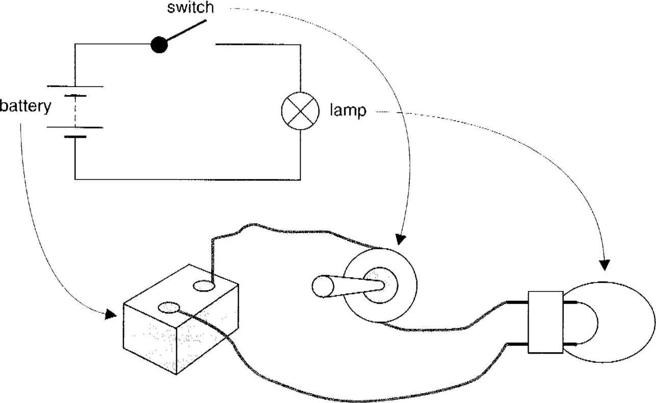
There are many types of circuit, depending on what signal system is to be used and the kind of information it must carry. All have evolved from the battery, switch and lamp circuit. The switch may have gone, replaced by a more complex arrangement, the principle though, remains. And the sourcing, or sending, of the signal may originate with a two-wire circuit, and end at the destination with a similar two-wire circuit, but in between—the transmission system—we could meet any number of methods and media through which the signal passes, e.g. wireless, fibre link, or satellite.
Injecting a signal into a length of wire is like launching a missile. It can be aimed with proper regard for its size and shape, how far it has to travel and through what. Or, it can be hurled without thought for any of these. Our lamp and battery circuit would be in the latter category if just made up of bits of wire and insulating tape. Although able to signal on or off, its usefulness would be somewhat limited.
Even so, the comprehensive world-wide system of cable telegraphy created in the nineteenth century is based on this simple circuit. Using a battery and switch to send a signal or current along the cable or wire and a sensitive indicator to replace the inefficient lamp, messages in simple code are sent under the sea and over land. While the ‘missile’ here may be thought of as crude and the path it passes along little better, cables have now been in use for over 150 years, so proving the technique to be a remarkably reliable means of communication. Couple this to its inherent security and resistance to interference and it is easy to see how valuable the cable telegraph was to become in times of international stress. A point to reflect on with the rapid growth of today's hi-tech eavesdropping.
The complexity of signals as used in audio and video require greater sophistication in their handling and transmission than yesterday's cable telegraph. In practice, the circuit is usually a fait accompli, often provided by a contractor. The actual line (as the cable is usually called) can be taken as conforming to a standard. The longer the line, of course, the more probable the chance of error or fault. Particularly so where the means of transmission changes from one system to another.
Comparing the circuit of battery, switch and lamp to a telegraph cable would be perfectly reasonable but the presence of a long interconnecting cable has to be considered. No cable or piece of wire is ever perfect. For short lengths, the metre or so of wire that makes up our basic lamp circuit, there is negligible effect on its operation. So simple a concept, however, starts to break down as the distance between the signal source and destination increases. In such a case, the connecting wire, whilst carrying the signal current, absorbs significant power from it.
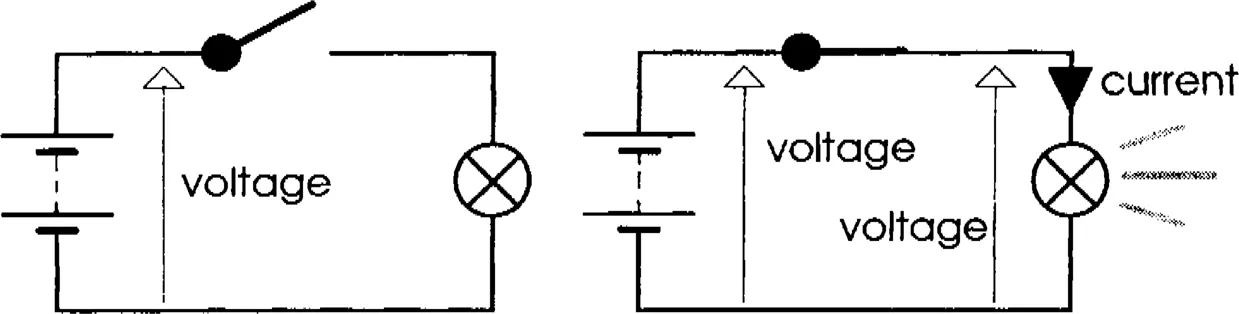
Figure 1.2 shows a schematic diagram of the simple circuit extended into a cable, and the operation of sending a simple ‘OFF-ON’ type of signal. Also shown in graphical form is the effect of time from the point of switching on and launching the signal into the cable to the signal's appearance at the destination. The finite transmission time taken by an electric current to travel from source to destination, although very fast—approaching the velocity of light—the effect is significant in electrical terms over long distances.

Applying our battery voltage at the sending end of the cable, the first thing to happen is the cable ‘starts to fill up with electricity’—a statement that simplifies the action but serves to illustrate the mechanism. The cable can, therefore, be said to have a capacity that must be filled before a signal can emerge at the far end. One can compare this to filling a pipe with fluid; quite a lot of fluid will go into a long pipe before any reaches the far end. But like all simple analogies, this one can be subject to misinterpretation, so avoid taking the idea too literally. It does, though, offer an alternative way to understanding in basic terms the concept of signal transmission over long distances.
Source and destination
In an ideal world the signal appearing at the destination will be identical to that sent out from the source. From the discussion so far, we can see this ideal is not possible. Yet as long as the degree of degradation or attenuation is known and understood, correction can be applied and a practical and predictable signal communication system will be achievable. But what must we do to bring this about? This question is the bottom line of all signal transmission, so let us list the key requirements of a circuit:
- The conditions, or characteristics, at the source and destination are known.
- The circuit cable and associated equipment are compatible.
- The circuit characteristics are known.
- The signal and circuit are compatible.
- The signal is able to carry the information required.
- The signal will be immune from interference.
- The circuit will be reliable.
- The information will be secure.
Requirements 1 to 5 embrace the technical requirements of the circuit design. Requirements 6, 7 and 8 are largely dependent on the kind of circuit used and here, reference to ‘circuit’ may in practice, go beyond the two-wire circuit considered so far. It is quite usual over long distances to have combinations of cable, wireless, fibre optic, or satellite-based systems. But Requirement 1 states that the source and destination characteristics should be known. If we also know Requirement 3, which sets out the characteristics of the circuit, we can predict how the circuit will react to, and alter, the signal.
Receiving a signal
Figure 1.2 shows the signal distortion caused by the time element and cable capacity. Let us assume that the cable design is optimised for the job it has to do. Now the two most significant parameters of the cable are:
- Cable resistivity: this causes signal power loss.
- Cable capacity: how much electric current flows into it before the signal can appear at the destination.
The propagation delay of Figure 1.2 is the time taken for the signal to appear at the destination. A hundred years ago this was of no great significance, but now it most certainly is. Absolute time is now a universal requirement, and whatever the means of transmission, time differences must be considered. Cables may be used over kilometres or just centimetres. The length will inevitably have considerable effect on the signal and its distortion. All cables, whatever the length, will affect the signal to some degree, but by careful design this can be minimised and made predictable. Cable design influences, in particular, how effectively the signal is able to carry information, as well as how far and how quickly. This is the cable characteristic. An integral part of a cable characteristic is to state how the cable is loaded, ...
Table of contents
- Cover Page
- Half Title Page
- Dedication
- Title Page
- Copyright Page
- Contents
- Preface
- Acknowledgements
- Introduction
- Part One The Foundation
- Part Two In Practice
- appendix
- glossary
- reference
- Index
Frequently asked questions
Yes, you can cancel anytime from the Subscription tab in your account settings on the Perlego website. Your subscription will stay active until the end of your current billing period. Learn how to cancel your subscription
No, books cannot be downloaded as external files, such as PDFs, for use outside of Perlego. However, you can download books within the Perlego app for offline reading on mobile or tablet. Learn how to download books offline
Perlego offers two plans: Essential and Complete
- Essential is ideal for learners and professionals who enjoy exploring a wide range of subjects. Access the Essential Library with 800,000+ trusted titles and best-sellers across business, personal growth, and the humanities. Includes unlimited reading time and Standard Read Aloud voice.
- Complete: Perfect for advanced learners and researchers needing full, unrestricted access. Unlock 1.4M+ books across hundreds of subjects, including academic and specialized titles. The Complete Plan also includes advanced features like Premium Read Aloud and Research Assistant.
We are an online textbook subscription service, where you can get access to an entire online library for less than the price of a single book per month. With over 1 million books across 990+ topics, we’ve got you covered! Learn about our mission
Look out for the read-aloud symbol on your next book to see if you can listen to it. The read-aloud tool reads text aloud for you, highlighting the text as it is being read. You can pause it, speed it up and slow it down. Learn more about Read Aloud
Yes! You can use the Perlego app on both iOS and Android devices to read anytime, anywhere — even offline. Perfect for commutes or when you’re on the go.
Please note we cannot support devices running on iOS 13 and Android 7 or earlier. Learn more about using the app
Please note we cannot support devices running on iOS 13 and Android 7 or earlier. Learn more about using the app
Yes, you can access An Introduction to Video and Audio Measurement by Peter Hodges in PDF and/or ePUB format, as well as other popular books in Languages & Linguistics & Communication Studies. We have over one million books available in our catalogue for you to explore.