![]() Chapter 1
Chapter 1
Material Science and Engineering![]()
The orientation analysis of the shear bands in cold-rolled ultra-low carbon steel using the EBSD technique
Wen-Fang. CUI*†, Yu-Hui SHA
Key Laboratory for Anisotropy and Texture of Materials
(Ministry of Education), Northeastern University,
Shenyang, 110819 China†E-mail: [email protected]
www.neu.edu.cn The morphologies and crystal orientations of the shear bands in cold-rolled ultra-low carbon steel were characterized by using TEM and EBSD technique. One important finding is that some shear bands develop in α orientated grains in addition to γ and rotated Goss orientated grains. Shear bands originate at grain boundaries and spread to ingrains. The shear bands in α and γ grains have {111} <112> and (110) [001] orientation, respectively, which conform to the preferential orientation of the recrystallization grains. It is believed that at the margin and in the interior of the shear bands in α grains are ideal recrystallization nucleation sites because there are large orientation gradient, strain gradient and lattice curvature in these regions. The present investigation provides an experiment evidence for clarifying the nucleation and crystal orientation of recrystallization grains during annealing.
Keywords: Steel; Cold working; Deformation structure; Lattice rotation; EBSD.
1.Introduction
Shear band refers to a localized shear structure with length limited within grain-scale. It is a kind of important microstructural morphology particularly formed at medium strains rolling due to plastic instability of metals. The researchers always show strong interest to the shear bands because they are not only a common microstructure just like deformation bands during heavy rolling [1–3], but also the orientation of shear bands has potential influence on the evolution of recrystallization texture [4]. Shear bands affect the distribution of stored strain energy and act as preferential nucleation sites for recrystallization grains in many cases [5]. Thus, investigating the formation, the development and the orientation change of the shear bands during rolling are of significance to the thermal mechanical process of various alloys.
It has been reported that shear bands generally form in those grains with γ fiber texture in cold-rolled bcc metal. Shen et al calculated the shear distribution in the deformed grains by using Taylor relaxed constraint model and Bishop & Hill maximum work principle [6]. They concluded that highly localized shearing only occurs in {111} <112> orientated grains. It is impossible for the occurrence of shear bands in other orientated grains because of homogeneous deformation in those grains. Li et al studied the microstructural evolution of IF-steel during cold rolling and found that only unidirectional geometrically necessary boundary (GNB) structure was frequently seen in α grains, but intersect dislocation walls structures or imposed shear bands (S-band) on a single set of GNB were seen in y grains [7]. Recently, Nguyen-Minh et al [8] investigated the shear bands in the rotated Goss ({110} <110>) orientation in Fe-1.2 mass % Si alloy. They predicted that the shear band rotates around the TD axis and finally involves into the cube component. Dorner et al [9, 10] thought that the new grains form in-between adjacent microshear bands in compressed Fe-3 mass % Si steel. This is attributed to the lattice rotation due to the activity of the second slip system in that area.
Up to date, most of investigations on the shear bands in bcc metals focus on the effects of deformation conditions on the microstructural features of shear bands in γ grains. Studies seldom pay attention to the shearing phenomenon in other oriented grains and the variation of the crystal orientation in-band. The aim of this study was to investigate the orientation of the shear bands in different orientated grain in the cold rolled ultra-low carbon steel and clarify the formation mechanisms of the shear bands based on plastic deformation theory of bcc metal.
2.Experimental
The chemical compositions (mass %) of the ultra-low carbon steel are: 0.037C, 0.21Mn, 0.02P, 0.001S, bal Fe. The hot-rolled slab was heated to 950°C followed by furnace cooling to 700°C, and then cold-rolled to 60% reduction. Deformed microstructure was observed by TEM (JEM-2100, Japan) operated at 200kV. The misorientation angles between shear band and matrix lattice were measured by convergent beam electron diffraction technique (CBED). The crystal orientations analysis was performed by SEM with EBSD system (JEOL-7001F, Japan). Orientation data were analyzed with Channel 5 software.
3.Results
3.1Morphology of shear bands
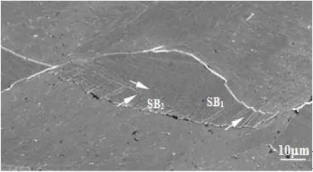
The morphology of the shear bands is shown in Fig. 1. In the “spindle” shape deformed grain, the parallel shear bands (SB1) with spacing 5μm initiate at grain boundary and spread to in-grain. Shear strain caused by localized slip is so large that “step” traces leave at grain boundaries. The shear bands are hindered in the middle part of the grain by another set of shear bands (SB2). Generally, multiple slip more frequently occurs at the areas near grain boundaries in polycrystalline metal in order to coordinate the deformation between adjacent grains. Shear bands should not develop at the grain boundaries. However, the grain boundary is a barrier for dislocation movement. Strain hardening at grain boundaries conversely promotes the formation of shear bands there [11].
Fig. 1 Morphologies of two sets of shear bands in a deformed grain.
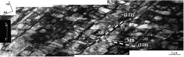
Fig. 2 displays TEM image of the deformed microstructure. It is seen so-called MB structure (microband) consisting of parallel GNBs. MBs incline to RD (rolling direction) at an angle of ~35°. Shearing bands have spacing of 1-2μm at an inclination angle of ~17° to RD. The formation of MBs is associated with less than five slip systems in γ grains [12]. MBs are intersected by shear bands into many small domains. Li et al thought that the divided regions provide sites for nucleation of γ-fiber grains during recrystallization [7]. However, we measured the misorientation angles between adjacent domains by CBED technology. The maximum misorientation angle is only 5°, indicating that the domains have almost the same orientation. It is difficult for recrystallization nucleation at such a shear band. The analysis is agreement with Quadir’s viewpoint [12]. In addition to this, the shear strain bore by single microshear band impossibly leaves “step” at grain boundary as seen in Fig. 1. The “step” might be caused by the aggregation of numerous “microshear” bands into “macroshear” bands. The crystal orientation analysis of “macroshear” bands was further studied by EBSD technique in the present paper.
Fig. 2 TEM image of microbands and microshear bands. The inclination angles of MBs and SBs to RD are 35° and 17°, respectively.
3.2Orientation analysis of the shear bands
Since homogeneous flow easily takes place in α grains due to seven slip systems, thus, it is generally accepted that α grains exhibit large cell structure. We calculated the shear strain distribution of bcc metal under various rolling conditions, and introduced slip fraction to characterize the contribution of slip plane to shear strain. The results showed that when ε31=0.2, the maximum slip fraction on {001} <110> and {112} <110> orientation reaches 0.8 and 0.9, respectively. This indicates that the highly localized shear strain also easily occurs in a orientated grain. The following orientation analysis of the shear bands confirms this.
Fig. 3 shows the orientation map of (001) [110] α orientated grain. The (200) pole figures and the misorientation angles between matrix and shear bands are superimposed on it. It is seen th...