![]()
CHAPTER 1
MECHANICAL SEALS
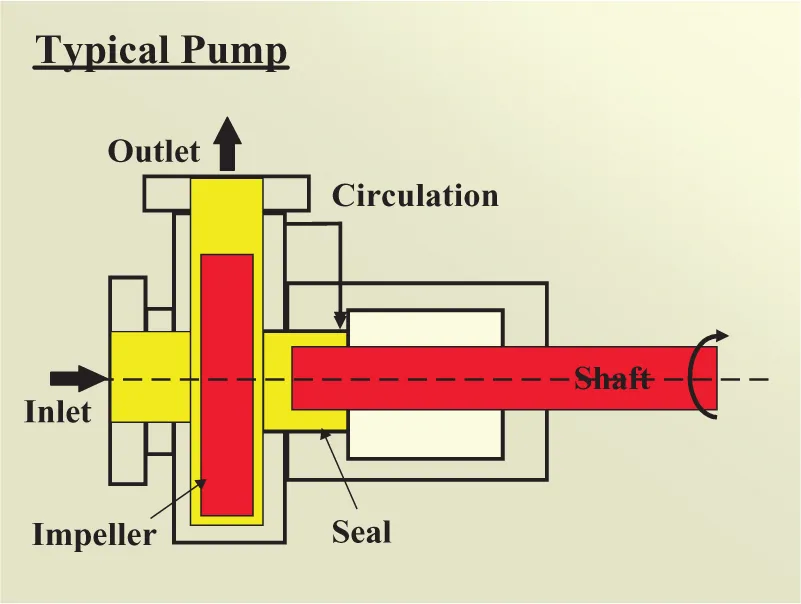
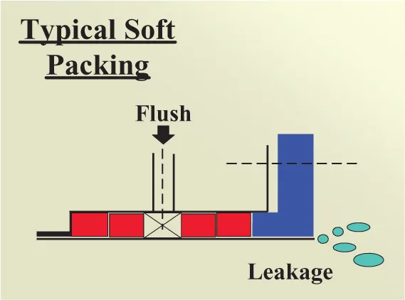
Before the advent of the mechanical seal, pump sealing was a problem, relying on the compression of packing around the shaft and within the stuffing box to make a seal. Frequent adjustment of the packing was necessary to effect sealing with resultant wear to both packing and shaft or shaft sleeve (Figures 1.1 and 1.2).
A patent granted in 1915 records one of the first attempts at the development of what is now known as the mechanical seal.
This patent (see Figure 1.3) described a device consisting of a rotating member (A), gasketed to the shaft (B), running against a stationary member (C), gasketed to the stuffing box (D), and some springs (E) to keep the faces against each other. The only path for any leakage to occur was therefore the plane of contact between the faces.
Figure 1.1. Typical pump
Figure 1.2. Package Sealing
Figure 1.3. Overview of package Sealing
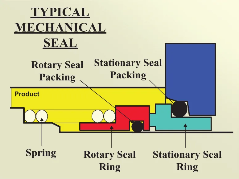
Much progress has been made in the design of mechanical seals since then, but the basic principle has remained unchanged (Figure 1.4).
Figure 1.4. Typical Mechanical Seal
The sealing function is accomplished by the gap between the faces; across this gap, the liquid pressure drops from full stuffing box pressure to the outside pressure. This gradual drop is called the “pressure gradient.”
Besides viscosity, many other factors act upon the liquid film, making the exact determination of the pressure gradient a very difficult problem.
Contrary to what many people believe, the mechanical seal must leak.
In order to get an acceptable running time out of a seal, the faces must be lubricated (Figure 1.5). Lubrication is carried out by the product forming a film between the faces.
Figure 1.5. Heat Dissipation
The second function of the film is heat dissipation.
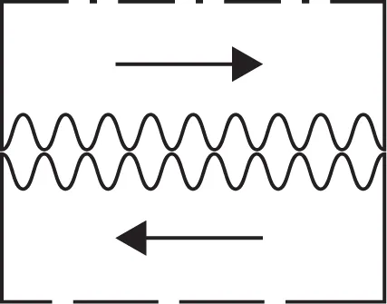
When the surfaces of two parts rub against each other, the movements have to overcome the friction between the two surfaces. The degree of friction depends on the smoothness of the surfaces and the materials of the two parts. Although it is possible to reach a high degree of smoothness on the surfaces, there will always be some deviation as is shown in an enlarged form in Figure 1.6. The high spots on the surfaces will cause friction; this friction will produce heat, and the faces will wear and may even become “pitted.”
Figure 1.6. Effects of High Spots
Figure 1.7. Reducing Friction
To reduce friction between the surfaces, we must prevent contact between them, and this can be done by means of a liquid film (see Figure 1.7). The film of liquid between the surfaces prevents metallic friction and replaces it with the considerably less liquid friction, thus producing less heat. The liquid film is provided by the actual product leakage.
In order to maintain the film of liquid between the faces, we must see to it that the force that is closing the faces (derived from the stuffing box pressure) does not become too high.
The successful operation of a mechanical seal depends on the presence and maintenance of an adequate film of liquid between the faces (Figure 1.8).
Figure 1.8. Importance of Adequate Oil Film
Its disappearance at any time will result in the faces rubbing against each other, causing excessive overheating and almost immediate failure of the seal. Insufficient leakage will cause an increase in internal fluid friction, also leading to overheating with consequent reduction in seal life and probable failure. Excessive leakage cannot be tolerated from the standpoint of production losses and/or safety. The mechanical seal’s function is to minimize leakage to acceptable levels.
UNBALANCED AND BALANCED MECHANICAL SEALS
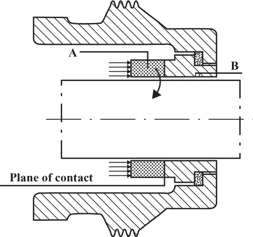
The successful operation of a mechanical seal depends on establishing a film of liquid of only a few microns thick between the faces. This would not be possible if the faces did not have an extremely smooth surface finish and were not running parallel to each other. Figures 1.9 and 1.10 show a typical unbalanced seal.
The term “hydraulic balance” when applied to mechanical seals is used to denote the relationship between the pressure being sealed (stuffing box pressure) and the seal-face-contact pressure. Seals are classified as “balanced” or “unbalanced,” but within each classification, there is a degree of balance or unbalance.
In Figure 1.9, the rotating seal ring (A) is pressed against the stationary seal ring (B) by the liquid pressure in the stuffing box and by the force exerted by one or more compression springs (springs are not shown, and other parts of the mechanical seal are also not shown). The pressure in the stuffing box and that exerted by the springs acts on the total area of the rotating seal ring, forcing against the stationary face of seal ring (B).
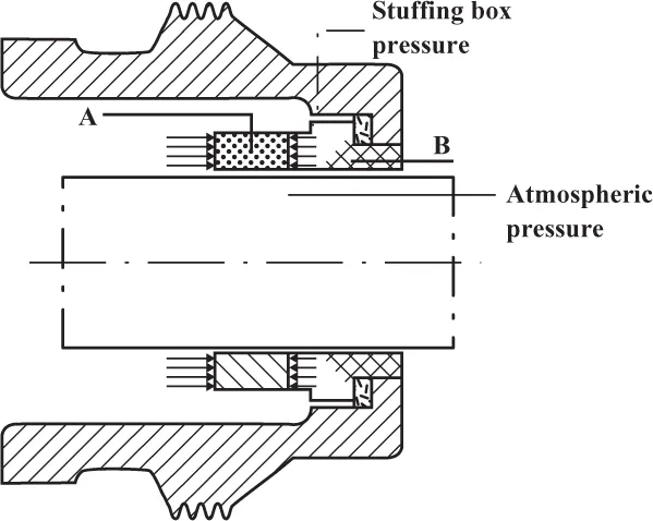
The liquid enters between the faces at stuffing box pressure and leaves at atmospheric pressure as shown in Figure 1.10. The pressure therefore decreases gradually across the sealing face and exerts considerably less force than the opposing direct stuffing box pressure. These two forces are now considered to be unbalanced as a net force acting against the seal faces that will increase as the stuffing box pressure increases.
Figure 1.9. Rotating Seal Ring
Figure 1.10. Effects of Decreasing Pressure
Because of the force exerted by the compression springs, the face-contact pressure in an unbalanced seal can be equal to the stuffing box pressure, that is, if the partial stuffing box pressure between the seal faces offsets the spring pressure, or it can be more than the stuffing box pressure if the pressure between the seal faces is less than the pressure exerted by the compression springs.
When the seal pressure reaches the p...