RF Circuit Design
eBook - ePub

RF Circuit Design

Christopher Bowick

  1. 256 Seiten
  2. English
  3. ePUB (handyfreundlich)
  4. Über iOS und Android verfügbar
eBook - ePub

RF Circuit Design

Christopher Bowick

Angaben zum Buch
Buchvorschau
Inhaltsverzeichnis
Quellenangaben

Über dieses Buch

It's Back! New chapters, examples, and insights; all infused with the timeless concepts and theories that have helped RF engineers for the past 25 years! RF circuit design is now more important than ever as we find ourselves in an increasingly wireless world. Radio is the backbone of today's wireless industry with protocols such as Bluetooth, Wi-Fi, WiMax, and ZigBee. Most, if not all, mobile devices have an RF component and this book tells the reader how to design and integrate that component in a very practical fashion. This book has been updated to include today's integrated circuit (IC) and system-level design issues as well as keeping its classic "wire lead" material. Design Concepts and Tools Include •The Basics: Wires, Resistors, Capacitors, Inductors•Resonant Circuits: Resonance, Insertion Loss •Filter Design: High-pass, Bandpass, Band-rejection•Impedance Matching: The L Network, Smith Charts, Software Design Tools•Transistors: Materials, Y Parameters, S Parameters•Small Signal RF Amplifier: Transistor Biasing, Y Parameters, S Parameters•RF Power Amplifiers: Automatic Shutdown Circuitry, Broadband Transformers, Practical Winding Hints•RF Front-End: Architectures, Software-Defined Radios, ADC's Effects•RF Design Tools: Languages, Flow, Modeling Check out this book's companion Web site at:

http://www.elsevierdirect.com/companion.jsp?ISBN=9780750685184 for full-color Smith Charts and extra content!

  • Completely updated but still contains its classic timeless information
  • Two NEW chapters on RF Front-End Design and RF Design Tools
  • Not overly math intensive, perfect for the working RF and digital professional that need to build analog-RF-Wireless circuits

Häufig gestellte Fragen

Wie kann ich mein Abo kündigen?
Gehe einfach zum Kontobereich in den Einstellungen und klicke auf „Abo kündigen“ – ganz einfach. Nachdem du gekündigt hast, bleibt deine Mitgliedschaft für den verbleibenden Abozeitraum, den du bereits bezahlt hast, aktiv. Mehr Informationen hier.
(Wie) Kann ich Bücher herunterladen?
Derzeit stehen all unsere auf Mobilgeräte reagierenden ePub-Bücher zum Download über die App zur Verfügung. Die meisten unserer PDFs stehen ebenfalls zum Download bereit; wir arbeiten daran, auch die übrigen PDFs zum Download anzubieten, bei denen dies aktuell noch nicht möglich ist. Weitere Informationen hier.
Welcher Unterschied besteht bei den Preisen zwischen den Aboplänen?
Mit beiden Aboplänen erhältst du vollen Zugang zur Bibliothek und allen Funktionen von Perlego. Die einzigen Unterschiede bestehen im Preis und dem Abozeitraum: Mit dem Jahresabo sparst du auf 12 Monate gerechnet im Vergleich zum Monatsabo rund 30 %.
Was ist Perlego?
Wir sind ein Online-Abodienst für Lehrbücher, bei dem du für weniger als den Preis eines einzelnen Buches pro Monat Zugang zu einer ganzen Online-Bibliothek erhältst. Mit über 1 Million Büchern zu über 1.000 verschiedenen Themen haben wir bestimmt alles, was du brauchst! Weitere Informationen hier.
Unterstützt Perlego Text-zu-Sprache?
Achte auf das Symbol zum Vorlesen in deinem nächsten Buch, um zu sehen, ob du es dir auch anhören kannst. Bei diesem Tool wird dir Text laut vorgelesen, wobei der Text beim Vorlesen auch grafisch hervorgehoben wird. Du kannst das Vorlesen jederzeit anhalten, beschleunigen und verlangsamen. Weitere Informationen hier.
Ist RF Circuit Design als Online-PDF/ePub verfügbar?
Ja, du hast Zugang zu RF Circuit Design von Christopher Bowick im PDF- und/oder ePub-Format sowie zu anderen beliebten Büchern aus Conception & Conception industrielle. Aus unserem Katalog stehen dir über 1 Million Bücher zur Verfügung.

Information

Verlag
Newnes
Jahr
2011
ISBN
9780080553429
CHAPTER 1 Components and Systems
Components, those bits and pieces which make up a radio frequency (RF) circuit, seem at times to be taken for granted. A capacitor is, after all, a capacitor—isn’t it? A 1-megohm resistor presents an impedance of at least 1 megohm—doesn’t it? The reactance of an inductor always increases with frequency, right? Well, as we shall see later in this discussion, things aren’t always as they seem. Capacitors at certain frequencies may not be capacitors at all, but may look inductive, while inductors may look like capacitors, and resistors may tend to be a little of both.
In this chapter, we will discuss the properties of resistors, capacitors, and inductors at radio frequencies as they relate to circuit design. But, first, let’s take a look at the most simple component of any system and examine its problems at radio frequencies.

WIRE

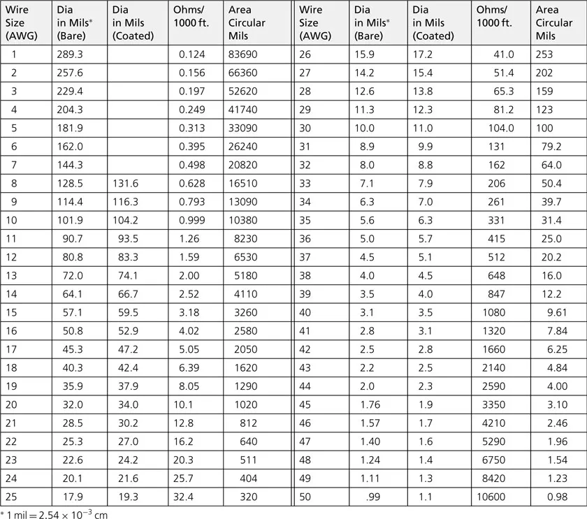
Wire in an RF circuit can take many forms. Wirewound resistors, inductors, and axial- and radial-leaded capacitors all use a wire of some size and length either in their leads, or in the actual body of the component, or both. Wire is also used in many interconnect applications in the lower RF spectrum. The behavior of a wire in the RF spectrum depends to a large extent on the wire’s diameter and length. Table 1-1 lists, in the American Wire Gauge (AWG) system, each gauge of wire, its corresponding diameter, and other characteristics of interest to the RF circuit designer. In the AWG system, the diameter of a wire will roughly double every six wire gauges. Thus, if the last six gauges and their corresponding diameters are memorized from the chart, all other wire diameters can be determined without the aid of a chart (Example 1-1).
TABLE 1-1. AWG Wire Chart
image
EXAMPLE 1-1
Given that the diameter of AWG 50 wire is 1.0 mil (0.001 inch), what is the diameter of AWG 14 wire?
Solution
AWG 50 = 1 mil
AWG 44 = 2 × 1 mil = 2 mils
AWG 38 = 2 × 2 mils = 4 mils
AWG 32 = 2 × 4 mils = 8 mils
AWG 26 = 2 × 8 mils = 16 mils
AWG 20 = 2 × 16 mils = 32 mils
AWG 14 = 2 × 32 mils = 64 mils (0.064 inch)

Skin Effect

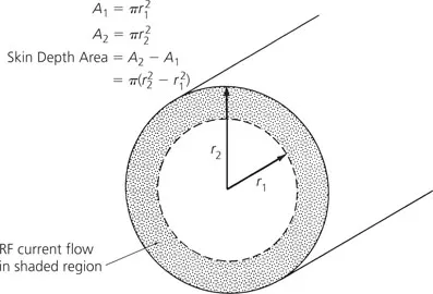
A conductor, at low frequencies, utilizes its entire cross-sectional area as a transport medium for charge carriers. As the frequency is increased, an increased magnetic field at the center of the conductor presents an impedance to the charge carriers, thus decreasing the current density at the center of the conductor and increasing the current density around its perimeter. This increased current density near the edge of the conductor is known as skin effect. It occurs in all conductors including resistor leads, capacitor leads, and inductor leads.
The depth into the conductor at which the charge-carrier current density falls to 1/e, or 37% of its value along the surface, is known as the skin depth and is a function of the frequency and the permeability and conductivity of the medium. Thus, different conductors, such as silver, aluminum, and copper, all have different skin depths.
The net result of skin effect is an effective decrease in the cross-sectional area of the conductor and, therefore, a net increase in the ac resistance of the wire as shown in Fig. 1-1. For copper, the skin depth is approximately 0.85 cm at 60 Hz and 0.007 cm at 1 MHz. Or, to state it another way: 63% of the RF current flowing in a copper wire will flow within a distance of 0.007 cm of the outer edge of the wire.
image
FIG. 1-1. Skin depth area of a conductor.

Straight-Wire Inductors

In the medium surrounding any current-carrying conductor, there exists a magnetic field. If the current in the conductor is an alternating current, this magnetic field is alternately expanding and contracting and, thus, producing a voltage on the wire which opposes any change in current flow. This opposition to change is called self-inductance and we call anything that possesses this quality an inductor. Straight-wire inductance might seem trivial, but as will be seen later in the chapter, the higher we go in frequency, the more important it becomes.
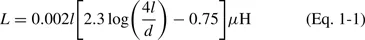
The inductance of a straight wire depends on both its length and its diameter, and is found by:
image
where,
L = the inductance in µH,
l = the length of the wire in cm,
d = the diameter of the wire in cm.
This is shown in calculations of Example 1-2.
EXAMPLE 1-2
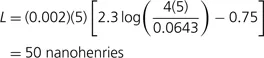
Find the inductance of 5 centimeters of No. 22 copper wire.
Solution
From Table 1-1, the diameter of No. 22 copper wire is 25.3 mils. Since 1 mil equals 2.54 × 10⁻³ cm, this equals 0.0643 cm. Substituting into Equation 1-1 gives
image
The concept of inductance is important because any and all conductors at radio frequencies (including hookup wire, capacitor leads, etc.) tend to exhibit the property of inductance. Inductors will be discussed in greater detail later in this chapter.

RESISTORS

Resistance is the property of a material that determines the rate at which electrical energy is converted into heat energy for a given electric current. By definition:
image
The thermal dissipation in this circumstance is 1 watt.
image
Resistors are used everywhere in circuits, as transistor bias networks, pads, and signal combiners. However, very rarely is there any thought given to how a resistor actually behaves once we depart from the world of direct current (DC). In some instances, such as in transistor biasing networks, the resistor will still perform its DC circuit function, but it may also disrupt the circu...

Inhaltsverzeichnis