Rail Vehicle Mechatronics
eBook - ePub

Rail Vehicle Mechatronics

Maksym Spiryagin, Stefano Bruni, Christopher Bosomworth, Peter Wolfs, Colin Cole

Buch teilen
  1. 440 Seiten
  2. English
  3. ePUB (handyfreundlich)
  4. Über iOS und Android verfügbar
eBook - ePub

Rail Vehicle Mechatronics

Maksym Spiryagin, Stefano Bruni, Christopher Bosomworth, Peter Wolfs, Colin Cole

Angaben zum Buch
Buchvorschau
Inhaltsverzeichnis
Quellenangaben

Über dieses Buch

This unique and up-to-date work surveys the use of mechatronics in rail vehicles, notably traction, braking, communications, data sharing, and control. The results include improved safety, comfort, and fuel efficiency.

Mechatronic systems are a key element in modern rail vehicle design and operation. Starting with an overview of mechatronic theory, the book covers such topics as modeling of mechanical and electrical systems for rail vehicles, open and closed loop control systems, sensors, actuators, and microprocessors. Modern simulation techniques and examples are included throughout the book. Numerical experiments and developed models for railway application are presented and explained. Case studies are used, alongside practical examples, to ensure that the reader can apply mechatronic theory to real world conditions. These case studies include modeling of a hybrid locomotive and simplified models of railway vehicle lateral dynamics for suspension control studies.

Rail Vehicle Mechatronics provides current and in-depth content for design engineers, operations managers, systems engineers, and technical consultants working with freight, passenger, and urban transit railway systems worldwide.

Häufig gestellte Fragen

Wie kann ich mein Abo kündigen?
Gehe einfach zum Kontobereich in den Einstellungen und klicke auf „Abo kündigen“ – ganz einfach. Nachdem du gekündigt hast, bleibt deine Mitgliedschaft für den verbleibenden Abozeitraum, den du bereits bezahlt hast, aktiv. Mehr Informationen hier.
(Wie) Kann ich Bücher herunterladen?
Derzeit stehen all unsere auf Mobilgeräte reagierenden ePub-Bücher zum Download über die App zur Verfügung. Die meisten unserer PDFs stehen ebenfalls zum Download bereit; wir arbeiten daran, auch die übrigen PDFs zum Download anzubieten, bei denen dies aktuell noch nicht möglich ist. Weitere Informationen hier.
Welcher Unterschied besteht bei den Preisen zwischen den Aboplänen?
Mit beiden Aboplänen erhältst du vollen Zugang zur Bibliothek und allen Funktionen von Perlego. Die einzigen Unterschiede bestehen im Preis und dem Abozeitraum: Mit dem Jahresabo sparst du auf 12 Monate gerechnet im Vergleich zum Monatsabo rund 30 %.
Was ist Perlego?
Wir sind ein Online-Abodienst für Lehrbücher, bei dem du für weniger als den Preis eines einzelnen Buches pro Monat Zugang zu einer ganzen Online-Bibliothek erhältst. Mit über 1 Million Büchern zu über 1.000 verschiedenen Themen haben wir bestimmt alles, was du brauchst! Weitere Informationen hier.
Unterstützt Perlego Text-zu-Sprache?
Achte auf das Symbol zum Vorlesen in deinem nächsten Buch, um zu sehen, ob du es dir auch anhören kannst. Bei diesem Tool wird dir Text laut vorgelesen, wobei der Text beim Vorlesen auch grafisch hervorgehoben wird. Du kannst das Vorlesen jederzeit anhalten, beschleunigen und verlangsamen. Weitere Informationen hier.
Ist Rail Vehicle Mechatronics als Online-PDF/ePub verfügbar?
Ja, du hast Zugang zu Rail Vehicle Mechatronics von Maksym Spiryagin, Stefano Bruni, Christopher Bosomworth, Peter Wolfs, Colin Cole im PDF- und/oder ePub-Format sowie zu anderen beliebten Büchern aus Technology & Engineering & Mechanical Engineering. Aus unserem Katalog stehen dir über 1 Million Bücher zur Verfügung.

Information

Verlag
CRC Press
Jahr
2021
ISBN
9781000486131

1Introduction to Rail Vehicle Mechatronics

DOI: 10.1201/9781003028994-1

1.1HISTORICAL REVIEW

The establishment of general mechatronics as a discipline has taken a long period of time. If we consider the history timeline, it has a strong connection with the development of automation and it can be easily divided into the following phases:
  • Phase 1: Automation of direct processes. This phase is dated to the end of the 18th century. In some cases, it can also be the time when students of some colleges started to study the discipline referred to as “electromechanics.”
  • Phase 2: Analogue automation. This phase started by the late 1920s and continued to be developed into the late 1940s.
  • Phase 3: Digital automation. Immediately after the first transistor was invented in 1947, the engineering world was focused on electronics and its application in a variety of industry fields.
  • Phase 4: Digital automation control. By the late 1960s, the Japanese engineer Tetsuro Mori from Yaskawa Electric Corporation was working on electronic controls for electric motors and at that time he introduced the term mechatronics which only covered a combination of mechanics and electronics. The major difference between earlier electromechanics and mechatronics as disciplines was that mechatronics provided much more flexibility in terms of system design and its operation.
  • Phase 5: Digital mechatronic control. This phase was introduced in the 1970s and it was still considered the digital automation control phase in most publications. However, the first 4-bit and 8-bit microprocessor chips introduced in 1971 and 1972, respectively, allowed moving away from the usage of mechanical mechanisms and devices and provided easy ways to program different tasks for mechatronic systems. The outcome of this was that mechatronic systems became more precise and faster in exercising control than their predecessors and, in addition, this made possible to introduce automatic data collection and reporting features in the design of mechatronic systems. At this stage, the transition of automatic and control engineering [1] to mechatronics can be observed.
  • Phase 6: The microprocessor mechatronic control. In the 1990s, mechatronics started to be more flexible by means of the usage of computerized systems that also included communication and networked technologies. This allowed mechatronics as a discipline to cover some additional knowledge areas such as information technologies, sensors, and actuators.
Mechatronics application for rail vehicles is a relatively new development in comparison with the general mechatronics discipline. Professor Roger Goodall published the history of railway vehicle design in 2009 [2], where the introduction of mechatronics as a separate design phase for railway vehicle design is referred to as the “Mechatronic Design Period” and is said to have started in the 1990s. He wrote [2]:
During the 1990s, in other industries such as the aircraft and automotive industries, the power that became available from designing the mechanical system in conjunction with the electronics, computing and control, i.e., the use of mechatronics, was realised in a variety of research and development programmes, Although the railway industry is, perhaps naturally, somewhat behind these other two industries, nevertheless a variety of developments are being considered currently which imply that a ‘mechatronic period’ is close to happening for railway vehicles.
Since then, the development of mechatronics for rail vehicle design has been rapidly progressing with the implementation of new methods and modeling techniques in addition to hardware developments. The major historical rail vehicle mechatronic system design topics are [340]:
  • Traction power systems
  • Wheel adhesion systems
  • Tilting systems
  • Active suspension systems
  • Active steering systems
  • Braking systems
  • Safety protection systems that provide protection against derailment
  • Automatic train control systems
  • Condition monitoring and fault detection
  • Rail vehicle testing and roadworthiness acceptance
Considering the current dynamics in the application of modern communication and measurement technologies and advanced diagnostic and control algorithms in rail vehicle operations, including artificial intelligence and big data processing, it seems inevitable that rail vehicles will become “increasingly mechatronic” which confirms a prediction made in [13].

1.2THEORETICAL ASPECTS FOR THE APPLICATION OF MECHATRONIC SYSTEM

Understanding design and modeling processes and the associated dynamic performance is fundamental for tasks associated with the rail vehicle mechatronic disciplines. The theoretical aspects for the practical application of mechatronic systems on rail vehicles can be defined based on the railway operational, safety, and performance requirements as presented in the next few subsections.

1.2.1STABILITY AND CURVING

Stability and curving are two important aspects of a railway vehicle's running dynamics. Unfortunately, they often lead to conflicting design requirements for the running gear. The term running gear refers to the ensemble of components in the vehicle responsible for the vehicle's running behavior. The running gear includes components such as wheelsets, bearings, suspensions, bogie frames, brakes, and traction bars. The design of the running gear involves finding a trade-off between good stability at high speed and satisfactory curving behavior. Active vehicle control, particularly active suspensions, is a way to remove this design conflict, so this is one of the main areas for the use of mechatronics in railway vehicles.

1.2.1.1Running Stability of a Railway Vehicle

Running stability is a term used by railway engineers in relation to a self-excited motion of the wheelsets and bogies consisting of the combination of lateral displacement and yaw rotation called hunting [4143]. This behavior is typical of rail vehicles equipped with solid wheelsets, i.e., pairs of conical wheels rigidly connected to a common axle, while other types of lateral oscillation may arise for vehicles with independently rotating wheels.
The hunting motion is strongly affected by the speed at which the vehicle runs over the track: at low speed, an oscillation originated by an initial disturbance (e.g., from track imperfections) will be sufficiently damped so that the vehicle will soon return to the unperturbed condition. However, above a threshold speed called critical speed, the motion arising from the initial disturbance will have a growing amplitude until it will be limited by the wheel flanges making contact with the rails. In this condition, the hunting motion can be so violent as to produce permanent deformation of the track and even lead to the derailment of the vehicle. It is therefore extremely important that the vehicle is designed to have a critical speed sufficiently higher than the maximum operational service speed.
It should be noted that the critical speed of a railway vehicle is affected by a number of parameters, of which the most important to mention here is the conicity of the wheel/rail couple [41]. Conicity can be described in simple terms as the rate of variation of the wheel's rolling radius with the lateral displacement of the wheelset relative to the track centerline. For the same mechanical design of the running gear, a lower critical speed can be expected for higher wheel conicity. Conicity is in turn affected by some geometrical parameters of the wheel/rail couple, namely wheel and rail profiles, track gauge, and the distance between the back of the flanges of the wheels. Although some of these parameters are well defined, others are not known precisely or will be subject to significant variation during the vehicle's service life. In particular, wheel wear results in a modification of the wheel profile and increased conicity. Therefore, the design of the running gear for stability has to be performed considering different conditions of wheel wear, including the condition of maximal wear before wheel reprofiling.
The parameters involved in the design of the running gear having the largest impact on running stability are the stiffness of the primary suspensions in longitudinal and lateral directions, the bogie wheelbase and, as already mentioned, conicity. In order to have a high critical speed, the vehicle should be designed to have stiff primary suspensions, a long bogie wheelbase and relatively low conicity. Unfortunately, all of these measures will have a negative effect on curving as discussed below. There are other design parameters of the running gear having influence on stability (one example being the inertia of the bogie), but they are not described here as they are less relevant to the design conflict between stability and curving.

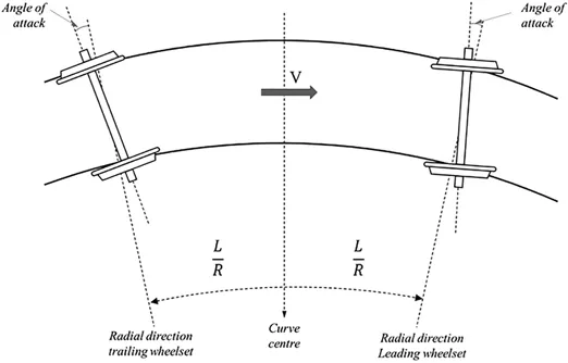
1.2.1.2Curving Behavior of a Railway Vehicle

A single, unconstrained solid wheelset with conical profiles running along a curve will naturally align its axis of revolution along a radial or nearly radial direction, minimizing the forces exchanged with the track [41]. However, some kind of connection between the wheelset and the car body shall be provided, either directly or through a bogie, to transfer efforts due to traction, braking and guidance and also, as discussed above, to meet requirements on vehicle stability. This connection is realized by suspensions establishing a flexible link between the wheelset and the car body directly (single stage of suspension) or between the wheelset and an intermediate body, the bogie frame, which is then connected to the car body by another stage of suspensions.
When two or more wheelsets are elastically connected with each other through the bogie or car body, the direction of their axes deviates significantly from the radial one and this is measured by the angle of attack, i.e., the angle formed by the axis of revolution of each wheelset and the local radial direction, as shown in Figure 1.1. The longer is the longitudinal distance L between two elastically connected wheelsets, the larger will be the angle of attack that can be expected for a given curve radius R.
FIGURE 1.1
FIGURE 1.1Angle of attack of a wheelset in a curve.
Due to the non-zero angle of attack, lateral creepages arise at wheel/rail contact interfaces, affecting wheel/rail forces in the lateral direction, which will be larger than what would be needed to balance the effect of centrifugal forces and track cant. Furthermore, the lateral force on the leading wheelset will push the wheelset out of the curve, causing contact of the flange of the outer wheel with the high rail. This in turn will produce a large variation of the rolling radius on the outer wheel, resulting in additional longitudinal creepage and hence longitudinal contact forces on both the inner and outer wheels of the leading wheelset and sometimes also in the trailing wheelset(s).
To sum up, having two or more wheelsets connected via elastic suspensions results in large wheel/rail contact forces that are not needed to balance other forces arising on the vehicle in the curve. These unnecessary forces may b...

Inhaltsverzeichnis