Chapter 1
Introduction
The design of overhead electrical transmission lines is an activity which involves contributions of many disciplines, both engineering and others. Movement of electric power requires supporting structures, conductors to carry the current, insulators to provide safe distance of charged conductors from supporting structures and appropriate connecting hardware all meeting standards for safety and reliability. Although transmission lines are primarily conduits of electrical energy, the design of those supporting structures calls for the involvement of civil engineers – structural and geotechnical.
This chapter takes a brief look at the origins of electrical transmission, the early structural systems used and the 100-year journey from those humble beginnings to the current world defined by technological advances and computers.
1.1 HISTORY OF ELECTRICAL TRANSMISSION
Count Alessandro Volta (1745−1827), the Italian physicist and inventor of the battery, was the first person to suggest the idea of a transmission line by writing in 1777 “… the igniting spark could be transported from Como to Milan with barbed wire supported by wooden poles planted here and there …” The structures in use those days for telegraph poles were wooden poles with zinc iron barbed wire supported by porcelain insulators fixed to the pole with screws and bolt hooks (TERNA, 2013).
The first industrial transmission line ran somewhere between Tivoli and Rome in 1882. The line carried a 5.1 kV single-phase circuit supported by metal fixtures made of double beams, concrete bases and insulators mounted on bolt hooks with wires made of copper. On September 16, 1882, Miesbach in Germany became the starting point for the first long distance transmission of electric power in the world. A 2.4-kilovolt direct current (DC) power transmission line transferred electricity from Miesbach over a distance of 31 miles (50 km) to Munich. However, the first long distance transmission of electrical energy occurred in 1884 during the Turin Expo. A 3 kV single phase current was sent over a 26-mile (42 km) line from Como to Lanzo, Italy. The supports were wooden poles and bell insulators with bronze wires were used.
The construction of the first three-phase 12 kV alternating current (AC) overhead transmission line took place in 1891 between Lauffen and Frankfurt, about 112 miles (180 km), coinciding with the International Electricity Exhibition in Frankfurt. Back in Italy, the Tivoli-Rome line was followed in 1898 with a 20-mile (32 km) line between Paderno and Milan: the first 3-phase circuit with metal pylons and delta-type multiple bell insulators with copper wires.
In the United States, the first power transmission line operated at 4 kV. It went into operation in June 1889 between Willamette Falls and downtown Portland in Oregon, running about 13 miles (21 km). In 1912, the first 110 kV overhead transmission line was constructed between Croton and Grand Rapids, Michigan. The year 1913 saw the construction of the biggest and longest high-voltage line – the 150 kV Big Creek Line in California – which spanned 250 miles (402 km).
The following years witnessed technical advances and rapid developments everywhere. The first 220 kV lines were constructed in Germany and Italy in 1928; by 1936, a 287 kV line was built between Hoover Dam in Nevada and Los Angeles, California. Sweden built the world’s first 380 kV line from Harsprannget to Stockholm, running 596 miles (959 km), in 1953. At the same time, American Electric Power (AEP) constructed the first 345 kV transmission line. In most cases, the average design spans between structures ranged from 1000 to 1500 ft (305 to 457 m); almost all lines used aluminum-steel conductors, bell insulators and latticed steel towers.
Hydro-Quebec in 1965 built Canada’s first 735 kV overhead line; soon, Russia and USA built overhead lines at 765 kV – then the largest voltage in the world. A 1200 kV line was commissioned in the Soviet Union (now Russia) in 1982.
1.2 TRANSMISSION STRUCTURES
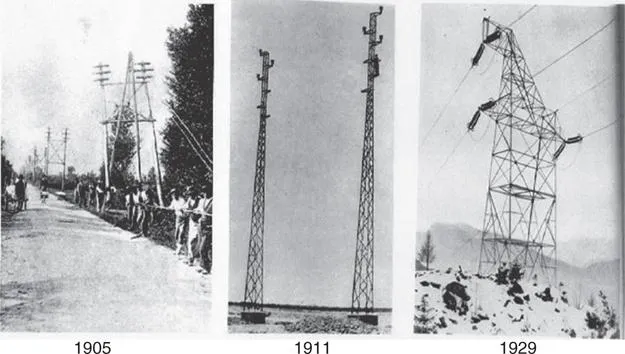
Historically, the term “transmission structures” usually implied iron or steel latticed towers. The early “pylons” dating back to 1829 were iron structures; the basic shape of later pylons was mostly inspired by the famous Eiffel Tower. Figure 1.1 shows some of the early shapes and forms of transmission structures.
Single wood poles directly-embedded into the ground formed the bulk of the transmission structures family for a greater part of the 20th century. France in the late 1900s and later Belgium in 1924 began producing concrete poles. The first steel tubular transmission pole in USA was erected in 1958.
Wood H-frames and lattice steel towers became popular later on, dictated mostly by height, availability, strength and urban convenience. Prestressed concrete poles are also used in various places. The world record for the largest transmission structure is now held by China’s 500 kV Yangtze River Crossing double-circuit tower, 1152 ft (351 m) tall, supporting a maximum span of 7667 ft (2337 m) and weighing 8.4 million lbs (3.81 million kgs).
Little historical information is available on how foundations were designed for transmission structures in the early days. It is conceivable that some rule of thumb and field tests were used while determining how much a pole needs to be embedded into the ground. One of the earliest discussions on soil behavior in wood H-frames can be traced to 1943 (Hughes Brothers, 1943). Figure 1.2 illustrates the earth pressures below the ground on the legs of an H-frame.
1.3 CURRENT STATE OF THE ART
The present state of technology encompasses a wide range of structural systems and configurations, materials, hardware and construction practices. The utility industry now uses wood poles (Figures 1.3a and b), tubular steel poles (Figures 1.4a, b and c) as well as steel lattice towers (Figure 1.5), spun prestressed concrete poles (Figure 1.6), laminated wood poles (Figure 1.7) and composite poles (Figures 1.8a and b) as primary structural elements. Fiberglass cross arms and braces are increasingly used on under-build distribution circuits on transmission poles. Helical screw anchors, easy to install in a variety of soils, are becoming very common in guying applications.
Figure 1.4d shows a typical reinforced concrete drilled shaft foundation for a steel pole. The main components of the foundation include a base plate welded to the pole bottom, anchor bolts connecting the base plate to the concrete pier and longitudinal ...