Practical Analog and RF Electronics
eBook - ePub

Practical Analog and RF Electronics

Daniel B. Talbot

  1. 212 pages
  2. English
  3. ePUB (adapté aux mobiles)
  4. Disponible sur iOS et Android
eBook - ePub

Practical Analog and RF Electronics

Daniel B. Talbot

DĂ©tails du livre
Aperçu du livre
Table des matiĂšres
Citations

À propos de ce livre

This is a book about real-world design techniques for analog circuits: amplifiers, filters, injection-locked oscillators, phase-locked loops, transimpedance amplifiers, group delay correction circuits, notch filters, and spectrum regrowth in digital radio frequency (RF) transmitters, etc.

The book offers practical solutions to analog and RF problems, helping the reader to achieve high-performance circuit and system design. A variety of issues are covered, such as:

  • How to flatten group delay of filters
  • How to use reciprocity to advantage
  • How to neutralize a parasitic capacitance
  • How to deepen a notch by adding only two components to the network
  • How to demodulate a signal using the secant waveform and its benefit
  • How to flatten the frequency response of a diode detector
  • When to use a transimpedance amplifier and how to maximize its performance
  • How to recover non-return-to-zero (NRZ) data when alternating current (AC) coupling is required
  • Why phase noise corrupts adjacent communication channels
  • Simple method to prevent false locking in phase-locked loops
  • How to improve the bandwidth of amplification by using current conveyors
  • A very simple impedance matching technique requiring only one reactive component
  • How to use optimization
  • Quadrature distortion and cross-rail interference

This book is meant to be a handbook (or a supplemental textbook) for students and practitioners in the design of analog and RF circuitry with primary emphasis on practical albeit sometimes unorthodox circuit realizations. Equations and behavioral simulations result in an abundance of illustrations, following a "words and pictures" easy-to-understand approach. Teachers will find the book an important supplement to a standard analog and RF course, or it may stand alone as a textbook. Working engineers may find it useful as a handbook by bookmarking some of the step-by-step procedures, e.g., the section on simplified impedance matching or group delay flattening.

Foire aux questions

Comment puis-je résilier mon abonnement ?
Il vous suffit de vous rendre dans la section compte dans paramĂštres et de cliquer sur « RĂ©silier l’abonnement ». C’est aussi simple que cela ! Une fois que vous aurez rĂ©siliĂ© votre abonnement, il restera actif pour le reste de la pĂ©riode pour laquelle vous avez payĂ©. DĂ©couvrez-en plus ici.
Puis-je / comment puis-je télécharger des livres ?
Pour le moment, tous nos livres en format ePub adaptĂ©s aux mobiles peuvent ĂȘtre tĂ©lĂ©chargĂ©s via l’application. La plupart de nos PDF sont Ă©galement disponibles en tĂ©lĂ©chargement et les autres seront tĂ©lĂ©chargeables trĂšs prochainement. DĂ©couvrez-en plus ici.
Quelle est la différence entre les formules tarifaires ?
Les deux abonnements vous donnent un accĂšs complet Ă  la bibliothĂšque et Ă  toutes les fonctionnalitĂ©s de Perlego. Les seules diffĂ©rences sont les tarifs ainsi que la pĂ©riode d’abonnement : avec l’abonnement annuel, vous Ă©conomiserez environ 30 % par rapport Ă  12 mois d’abonnement mensuel.
Qu’est-ce que Perlego ?
Nous sommes un service d’abonnement Ă  des ouvrages universitaires en ligne, oĂč vous pouvez accĂ©der Ă  toute une bibliothĂšque pour un prix infĂ©rieur Ă  celui d’un seul livre par mois. Avec plus d’un million de livres sur plus de 1 000 sujets, nous avons ce qu’il vous faut ! DĂ©couvrez-en plus ici.
Prenez-vous en charge la synthÚse vocale ?
Recherchez le symbole Écouter sur votre prochain livre pour voir si vous pouvez l’écouter. L’outil Écouter lit le texte Ă  haute voix pour vous, en surlignant le passage qui est en cours de lecture. Vous pouvez le mettre sur pause, l’accĂ©lĂ©rer ou le ralentir. DĂ©couvrez-en plus ici.
Est-ce que Practical Analog and RF Electronics est un PDF/ePUB en ligne ?
Oui, vous pouvez accĂ©der Ă  Practical Analog and RF Electronics par Daniel B. Talbot en format PDF et/ou ePUB ainsi qu’à d’autres livres populaires dans Technik & Maschinenbau et Elektrotechnik & Telekommunikation. Nous disposons de plus d’un million d’ouvrages Ă  dĂ©couvrir dans notre catalogue.

Informations

Éditeur
CRC Press
Année
2020
ISBN
9781000178425

1
Operational, RF, and Current Amplifiers and Their Ubiquity

1.1 Introduction

Operational amplifiers, inverting and non-inverting mode and the reason the latter exhibits better signal-to-noise ratio (SNR), and operational transconductance amplifiers (OTAs) and class-C and F high-efficiency amplifiers are explained in this chapter. Reciprocal networks allow input and output terminals to be swapped without consequence to gain in an op-amp application, but with a possible consequence to noise.
A short-cut is presented using the Miller equation to “back-of envelope” calculate closed-loop gain. The Miller effect is useful for capacitor neutralization.
Description of the transistor as either a current conveyor (grounded base or gate) or as a transconductance amplifier (grounded emitter or source) is provided. High bias current for improving SNR is discussed, with concomitant discussion of shot and resistor noise.
This chapter also includes discussion of gyrators to synthesize inductors.
A high-frequency amplifier circuit is used that is a two-transistor Darlington with feedback. The circuit is modeled and analyzed.
The current conveyor is discussed and its advantage for both high gain-bandwidth (GBW) and high dynamic range. By handling signal currents rather than voltages, one largely escapes the Miller effect.
Simulation Program with Integrated Circuit Emphasis (SPICE) calculations of the linearity of the open-loop nature of a current conveyor and closed-loop nature of an op-amp are compared.
Cascode circuits are not immune from the Miller effect in layout.

1.2 The Op-Amp and Its Real and Imaginary Parasitics and Compensation

The symbol for a standard op-amp is shown in Figure 1.1. Two inputs are shown; one is the non-inverting (+) and the other (-) is the inverting input. The output is the difference of the two input voltages at those ports multiplied by the gain (A) of the op-amp. As shown, there may be a shutdown input which turns the amplifier on or off, and when in the off state, the output is usually forced to become an open circuit. There are of course power supply terminals, which may be bipolar or unipolar, and when the former, they form a pair. Typical values are +15 and −15 volts or higher, but they can be as low as +5 and −5 volts or lower. In some cases, only one supply terminal (also called a rail) exists and the op-amp output can then have only one polarity (unipolar). So much for the idealized case. The practical case has limited bandwidth, slew rate, (common mode rejection ratio (CMRR), power supply rejection ratio (PSRR), output current available, input noise voltage, input noise current, supply current drain, input balance (offset), behavior over temperature, and process (e.g., silicon-germanium, metal-oxide-semiconductor (CMOS), standard silicon bipolar junction transistor (BJT)-based), input bias current, survivability to electromagnetic or gamma pulse (EMP) via a process called dielectric isolation, and the ability to handle large input common mode and or differential input voltages). One of the first commercial op-amps to exploit integrated circuit technology was the uA709, designed by Robert Widlar [1, 2]. The schematic diagram is shown in Figure 1.2.
FIGURE 1.1
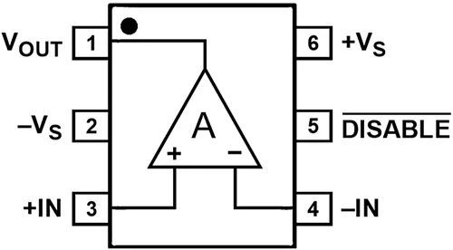
Op-amp with shutdown.
FIGURE 1.2
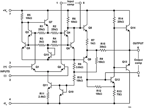
Schematic of ua709 op-amp, requiring external compensation capacitor.
A model of a practical op-amp is shown in Figure 1.3. It features a gain term G, an input resistance RI, an output resistance RO, and a gain-bandwidth product (GBW) F.
FIGURE 1.3
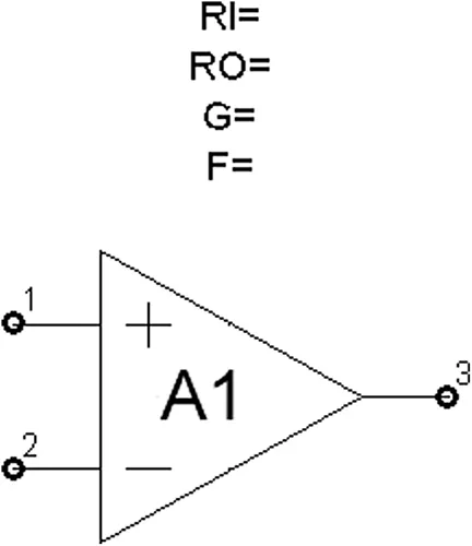
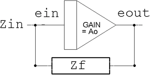
Practical op-amp model, open loop.
This op-amp can be configured per the example of Figure 1.4 to have a closed-loop gain of 101, and a 3 dB bandwidth of 300 MHz divided by 101, or about 3 MHz (see Figure 1.5). In this configuration, closed-loop gain at zero Hz is given as:
FIGURE 1.4
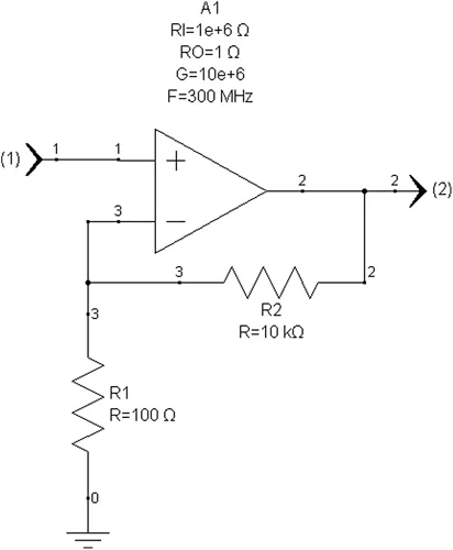
Closed-loop gain of 101 at zero Hz.
FIGURE 1.5
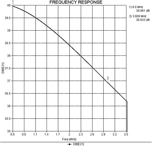
Closed-loop bandwidth of circuit of Figure 1.4.
G closed = 1 + R 2 R 1 (1.1)
assuming very large open-loop gain G. We can be more precise by factoring in some “back of the envelope” calculations based on the Miller effect, which we will describe as follows. When an op-amp is configured with a solitary feedback impedance as in Figure 1.6, the effective input impedance is equal to:
FIGURE 1.6
The Miller effect.
â„€ I N = â„€ F 1 − A (1.2)
See Figure 1.7. If the op-amp gain is negative (inverting) 1000 (for example) and the feedback network comprises a resistor o...

Table des matiĂšres

  1. Cover
  2. Half-Title
  3. Title
  4. Copyright
  5. Dedication
  6. Contents
  7. Preface
  8. About the Author
  9. 1 Operational, RF, and Current Amplifiers and Their Ubiquity
  10. 2 Transimpedance Amplifiers for Low Noise
  11. 3 Voltage-Controlled Amplifiers
  12. 4 Emitter Followers and Source Followers (FETs)
  13. 5 Equally Terminated Two-Port Reciprocal Networks and Reversal of Input and Output
  14. 6 Importance of Terminating Filters Properly
  15. 7 Diode Detector Flatness
  16. 8 Passive Filters
  17. 9 Secant Waveform for Synchronous Demodulation
  18. 10 Receiving NRZ Data Using AC Coupling
  19. 11 Gilbert Gain Cell Versus RF Mixer
  20. 12 Passive Components
  21. 13 Unwanted Sidebands Effect on Adjacent Channel(s)
  22. 14 Injection Locking
  23. 15 Phase-Locked Loops
  24. 16 Distortion Fundamentals and Spectral Regrowth
  25. 17 Optimization
  26. 18 Quadrature Distortion and Cross-Rail Interference
  27. Bibliography
  28. Index
Normes de citation pour Practical Analog and RF Electronics

APA 6 Citation

Talbot, D. (2020). Practical Analog and RF Electronics (1st ed.). CRC Press. Retrieved from https://www.perlego.com/book/1683862/practical-analog-and-rf-electronics-pdf (Original work published 2020)

Chicago Citation

Talbot, Daniel. (2020) 2020. Practical Analog and RF Electronics. 1st ed. CRC Press. https://www.perlego.com/book/1683862/practical-analog-and-rf-electronics-pdf.

Harvard Citation

Talbot, D. (2020) Practical Analog and RF Electronics. 1st edn. CRC Press. Available at: https://www.perlego.com/book/1683862/practical-analog-and-rf-electronics-pdf (Accessed: 14 October 2022).

MLA 7 Citation

Talbot, Daniel. Practical Analog and RF Electronics. 1st ed. CRC Press, 2020. Web. 14 Oct. 2022.