Physics
Doppler Effect in Light
The Doppler effect in light refers to the change in frequency or wavelength of light waves as a result of relative motion between the source of the light and the observer. Similar to the Doppler effect in sound, this phenomenon causes a shift in the perceived color of the light, with the light appearing more blue if the source is moving towards the observer and more red if it is moving away.
Written by Perlego with AI-assistance
Related key terms
1 of 5
10 Key excerpts on "Doppler Effect in Light"
 eBook - PDF
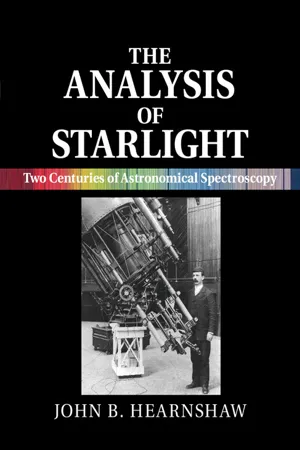
The Analysis of Starlight
Two Centuries of Astronomical Spectroscopy
- John B. Hearnshaw(Author)
- 2014(Publication Date)
- Cambridge University Press(Publisher)
6 • The Doppler effect 6.1 E A R L Y H I S T O R Y O F T H E D O P P L E R E F F E C T An important chapter in the history of astronomical spec- troscopy opened on 25 May 1842. On this day Christian Doppler (1803–53) (Fig. 6.1), the professor of mathematics at the University of Prague (then part of Austria), delivered a lecture to the Royal Bohemian Scientific Society entitled ‘Concerning the coloured light of double stars and of some other heavenly bodies’ [1]. By analogy both with sound and waves in the sea, Doppler maintained that light waves undergo a change in frequency of oscillation, and hence of colour, either when the luminous source or the observer is in motion relative to the aether (whose existence was at that time supposed necessary for the transport of light waves). He gave formulae for the frequency change ν when either the source or observer were in motion, and these amounted to a statement of the now familiar equation ν/ν 0 = V /c. Here V is the relative speed in the line of sight, c is the speed of light, and ν 0 is the light wave’s frequency for sources at rest. Doppler then made two incorrect assumptions: first, that the radiation from stars was largely confined to the visual region of the spectrum, and secondly that the space motions of the stars were frequently a significant fraction of the speed of light. As a consequence, stars normally appear- ing white are seen instead as strongly coloured, either vio- let or red, depending on their approach towards or reces- sion from Earth. Moreover, the brightness of fast-moving stars also depends on their velocity of recession or approach. If this latter parameter is large enough in either direction, then a star would become fainter or even invisible, when the light is shifted entirely out of the visible part of the spec- trum. eBook - PDF
Satellite Geodesy
Foundations, Methods, and Applications
- Günter Seeber(Author)
- 2008(Publication Date)
- De Gruyter(Publisher)
6 Doppler Techniques The Doppler effect or Doppler shift , named after the Austrian physicist Christian Doppler (1803–1853), denotes the difference between the frequency of the radiation received at a point and the frequency of the radiation at its source, when observer and source are moving with respect to each other (e.g. NGS, 1986). The effect is well known from the fact that an acoustic signal, emitted by a vehicle passing the observer with high speed, shifts suddenly from a higher to a lower tone. When the vehicle is approaching, the observer receives a higher frequency compared to a non-moving source; and with increasing range a lower frequency is observed (Fig. 6.1). It is evident that the frequency shift depends on the relative velocity between source and observer. T λ 1 λ 2 T Figure 6.1. Doppler effect Observation techniques based on the Doppler principle are widely used in science and technology for the determination of velocities. In astronomy the radial veloc-ity of distant cosmic objects can be derived from the Doppler shift of spectral lines (e.g. red shift of galaxies). In navigation velocity over the ground can be obtained by using the Doppler effect ( Doppler log ). In space technology and satellite geodesy Doppler observations played an important role from the beginning, because most of the early satellites transmitted on a stable frequency. Velocity changes, and hence orbital elements, could be derived from the measured frequency shift with rather simple equip-ment. Using these techniques the orbital elements of the very first artificial satellites were determined and published without any other information (Priester, Hergenhahn, 1958). The frequency shift caused by the Doppler effect can be described as a function of time (Fig. 6.2), and yields a characteristic curve. The Doppler curve of an artificial satellite lies in between curves (2) and (3), depending on the satellite’s range and altitude.
- David Halliday, Robert Resnick, Jearl Walker(Authors)
- 2023(Publication Date)
- Wiley(Publisher)
Such a Doppler shift is described as being a red shift, where red does not mean the measured wavelength is red or even visible. The term merely serves as a memory device because red is at the long-wavelength end of the visible spectrum. Thus λ is longer than λ 0 . Similarly, for a decreasing sep- aration, λ is shorter than λ 0 , and the Doppler shift is described as being a blue shift. Low-Speed Doppler Effect For low speeds (β ⪡ 1), Eq. 37.5.1 can be expanded in a power series in β and approximated as f = f 0 (1 − β + 1 _ 2 β 2 ) (source and detector separating, β ⪡ 1). (37.5.3) The corresponding low-speed equation for the Doppler effect with sound waves (or any waves except light waves) has the same first two terms but a different coefficient in the third term. Thus, the relativistic effect for low-speed light sources and detectors shows up only with the β 2 term. A police radar unit employs the Doppler effect with microwaves to measure the speed v of a car. A source in the radar unit emits a microwave beam at a certain (proper) frequency f 0 along the road. A car that is moving toward the unit inter- cepts that beam but at a frequency that is shifted upward by the Doppler effect due to the car’s motion toward the radar unit. The car reflects the beam back toward the radar unit. Because the car is moving toward the radar unit, the detector in the unit intercepts a reflected beam that is further shifted up in frequency. The unit compares that detected frequency with f 0 and computes the speed v of the car. Astronomical Doppler Effect In astronomical observations of stars, galaxies, and other sources of light, we can determine how fast the sources are moving, either directly away from us or directly toward us, by measuring the Doppler shift of the light that reaches us. If a certain star were at rest relative to us, we would detect light from it with a certain proper frequency f 0 . eBook - PDF
Transesophageal Echocardiography Multimedia Manual
A Perioperative Transdisciplinary Approach
- André Denault, Pierre Couture, Annette Vegas, Jean Buithieu, Jean-Claude Tardif, André Y. Denault, André Y. Denault, Pierre Couture, Annette Vegas, Jean Buithieu, Jean-Claude Tardif(Authors)
- 2016(Publication Date)
- CRC Press(Publisher)
2 Basic Principles of Doppler Ultrasound Pierre-Guy Chassot University of Lausanne, Lausanne, Switzerland Claude Tousignant St. Michael’s Hospital, University of Toronto, Toronto, Ontario, Canada DOPPLER EFFECT The Doppler effect is a well-known phenomenon: the sound of a train whistle has a higher pitch when the train is traveling toward the listener than when mov- ing away, though the emitting frequency remains the same. In 1842, the Austrian physicist Johann-Christian Doppler, studying the direction of movement of stars, mathematically described this frequency shift of recorded waves when a luminous or acoustic source, in relative motion, is compared with the stationary observer. The speed of traveling waves (c), such as light, sound, or ultrasound, is constant through a deter- mined medium and depends on the characteristics of this medium. When the emitting source is in motion, regardless of its speed, the sound waves are “compressed” in front of the transmitter, which is “catching up” with the transmitted waves it has produced (Fig. 2.1A). When the source moves slightly toward the stationary receiver before emitting the next wave, the two wave peaks are closer together when they reach the receiver (observer), where the wave- length (l) is shortened and the frequency ( f ) is increased (1). This happens because the product of l and f is a constant wave propagation of speed c: c ¼ f l (2:1) If the source moves away, the opposite occurs: l increases and f decreases.
- Daniel Fleisch, Julia Kregenow(Authors)
- 2013(Publication Date)
- Cambridge University Press(Publisher)
So in this case you measure a shorter wavelength and a higher frequency than the “true” values. 7 Likewise, if the source of the waves is mov-ing away from you, the waves appear stretched out and the wave crests and troughs arrive less frequently than if the source were stationary. So for a reced-ing source you measure a longer wavelength and a lower frequency than the true values. Since blue light has shorter wavelength and higher frequency than red light, the light from approaching objects is said to be “blueshifted,” and the light from receding objects is said to be “redshifted.” In astronomy, this terminology is used even if the waves are not in the visible portion of the spectrum – a shift toward longer wavelengths is called a redshift and a shift toward shorter wave-lengths is called a blueshift even if the waves are radio waves or X-rays. The Doppler effect also occurs when it’s you (the observer) that’s moving rather than the source – if you’re moving toward the source, its light will appear blueshifted and if you’re moving away from the source, its light will appear redshifted. All that matters is the relative speed between you and the source. 7 The “true” values of wavelength and frequency are the values that are sent out by the source. 3.3 Doppler shift 87 3.3.2 The Doppler equation The equation relating the “apparent wavelength” (that is, the wavelength mea-sured by the observer, λ app ) to the “true wavelength” (the wavelength given off by the source, λ true ) depends on two speeds: the speed of the source relative to the observer and the speed of the wave. For light, the speed of the wave in empty space is always c , and if the recession speed (defined as the speed with which an object is moving away from the observer) is v rec , then the Doppler-shift equation may be written as λ app λ true = 1 + v rec c . eBook - PDF
- Otto Laporte(Author)
- 2012(Publication Date)
- Academic Press(Publisher)
From the point of view of classical kinematics it was difficult to reconcile aberration with the universality of c. Now we recognize it to be a necessary consequence of the fact that the light velocity is independent of the reference system. In the following paragraph aberration will come up again in connection with a more general point of view. 1 1 . The Doppler Effect The elementary explanation of the Doppler effect is well known. If a light source which is at rest emits waves of period r, then the number of oscillations which meet a stationary observer during a time interval tsN = tx. But if the observer moves toward the wave with a velocity v, thus covering 1 1 . 4 THE DOPPLER EFFECT 67 a distance vt in time t, he will meet an additional vtX oscillations. eBook - PDF
- T. M. Helliwell, V. V. Sahakian(Authors)
- 2020(Publication Date)
- Cambridge University Press(Publisher)
(2.130) is taken to be positive and it is assumed that the beam does arrive at O . In short, this applies when the distance between the two observers is shrinking. The frequency received is greater than the frequency emitted, ν > ν , known as a blueshift, for obvious reasons. To see the other possibility – i.e., Oand O moving away from each other – we can simply flip the sign of β in this expression: ν ν = 1 − β 1 + β < 1 receding observers. (2.134) Now the distance between the two observers is increasing, and we find that the received frequency is less than the emitted one: we say there has been a redshift . Doppler shifts for light are an extremely useful tool in physics and technology, from determining the speeds of stars in distant galaxies leading to Hubble’s discovery of the expanding universe, to the use of frequency shifts in the GPS for location and navigation. If such special-relativistic effects were not included in GPS navigation, there would be large errors in position measurements. Interestingly, it even turns out to be equally essential for GPS to include additional effects due to earth’s gravity, as contained in Einstein’s general theory of relativity. 98 2 Relativity Minkowski Diagrams A particularly useful way to depict relativistic dynamics involves a visual tool called a Minkowski diagram. Simply put, it is a plot of the trajectory of a particle on a graph where the horizontal axis is one of the spatial directions and the vertical axis represents time, or actually the product c t. Figure 2.8 shows an example. Light cone Particle trajectory An event Light ray Light ray Fig. 2.8 A point on a Minkowski diagram represents an event. A particle’s trajectory appears as a curve with a slope that exceeds unity everywhere. The trajectory of the particle appears as a line moving upward, forward in time. It is sometimes referred to as the worldline of the particle. Light rays appear on such a diagram as straight lines at 45 ◦ , as shown in the figure. eBook - PDF
Numerical Simulations
Applications, Examples and Theory
- Lutz Angermann(Author)
- 2011(Publication Date)
- IntechOpen(Publisher)
For clarity, all photon paths were rotated afterwards as if the photons had emerged on the +X-axis. Photoacoustics has been added to simulate the acoustic response to pulsed light. Frequency modulation is a modality adding extra information using path length-dependent phase delay information. Here we only deal shortly with LDF. As mentioned previously, LDF makes use of the Doppler effect encountered with scattering of photons in particles when those particles are moving. The principles are shown in Figure 7. Using the definitions of the variables given in that Figure, the Doppler frequency is given by: ( ) 0 D s ω = − • k k v , (10) and with: 1 2 2 .sin k δ θ = k , (11) we find: 1 2 sin .cos D kv f θ α π = . (12) When applied to tissue, frequently the angles θ and α might be considered randomised. This is due to three reasons: -Preceding scattering by non-moving particles might cause the direction of the photons to be randomised upon encountering moving particles Numerical Simulations - Applications, Examples and Theory 160 Fig. 7. Principles of LDF. The particle has a velocity v . Vectors k 0 and k s denote the incoming and scattered light wave vectors, and δ k is the difference vector. -Most important moving particles are blood cells in capillaries. Due to the (more or less) random orientation of the capillaries the velocities will have random directions -Travelling from injection point to detection point, in general the photons will encounter many Doppler scattering effects, with random velocities and orientations All three effects will broaden the Doppler frequency distribution, which ideally would consist of one single peak, to a smooth distribution as in Figure 8. This means that it is not possible to measure the local velocity, but we only may extract information about the averaged velocity over the measuring volume. The averaging concerns the three effects mentioned above. eBook - PDF
- David Halliday, Robert Resnick, Kenneth S. Krane(Authors)
- 2019(Publication Date)
- Wiley(Publisher)
40. Show that, for speeds u c, the Doppler shift can be writ- ten in the approximate form where is the change in wavelength. 41. A rocket ship is receding from Earth at a speed of 0.20c. A light in the rocket ship appears blue to passengers on the ship. What color would it appear to be to an observer on Earth? (See Fig. 39-6.) 42. A spaceship, moving away from Earth at a speed of 0.892c, reports back by transmitting on a frequency (measured in the spaceship frame) of 100 MHz. To what frequency must Earth receivers be tuned to receive these signals? 43. In the spectrum of quasar 3C9, some of the familiar hydrogen lines appear but they are shifted so far toward the red that their wavelengths are observed to be three times as large as that observed in the light from hydrogen atoms at rest in the laboratory. (a) Show that the classical Doppler equation, which assumes that light behaves like sound, gives a velocity of recession greater than c. (b) Assuming that the relative mo- tion of 3C9 and the Earth is entirely one of recession, find the recession speed predicted by the relativistic Doppler equation. 44. The “red shift” of radiation from a distant galaxy consists of the light H , known to have a wavelength of 434 nm when observed in the laboratory, appearing to have a wavelength of 462 nm. (a) What is the speed of the galaxy in the line of sight relative to the Earth? (b) Is the galaxy approaching or receding? 45. Calculate the Doppler wavelength shifts expected for light of wavelength 553 nm emitted from the edge of the Sun’s disk at the equator due to the Sun’s rotation. See Appendix C for needed data. 46. With what speed would you have to go through a red light in order to have it appear green? Take 620 nm as the wavelength of red light and 540 nm as the wavelength of green light. u c , 47. In the experiment of Ives and Stilwell, the speed u of the hy- drogen atoms in a particular run was 8.65 10 5 m /s. eBook - ePub
- Jeffrey Forshaw, Gavin Smith(Authors)
- 2014(Publication Date)
- Wiley(Publisher)
t . Therefore the perceived time interval between the start and the end of the tick is(6.8 )It is very important to be clear that this extra slowing down of the clock is an ‘optical illusion’, in contrast to the time dilation effect which is a real slowing down of time. To emphasise this point, if light travels at a finite speed then moving clocks will appear to run slow even in classical theory such that Δt see = Δt ′(1 + v/c ).Eq. (6.8) leads us on nicely to the Doppler effect for light. Let us consider the situation illustrated in Figure 6.4 . A light source is at rest in S ′ and is being watched by someone at rest in S . The time interval Δt ′ could just as well be the time between the emission of successive peaks in a light wave, i.e. the frequency of the wave is f ′ = 1/Δt ′. The person watching the light source will instead see a frequency f = 1/Δt . The two frequencies are related using Eq. (6.8) :Figure 6.4 A light source of frequency f ′ at rest in S ′(6.9 )This is the result in the case that the light source is moving away from the observer, in which case Eq. (6.9) tells us that f < f ′ and so the light appears shifted to shorter frequencies, i.e. it is ‘red-shifted’. If the source is moving towards the observer we should reverse the sign of v in Eq. (6.9) and therefore conclude at f > f ′, i.e. the light is now ‘blue-shifted’.Example 6.1.2 How fast must the driver of a car be travelling towards a red traffic light (λ = 675 nm ) in order for the light to appear amber (λ = 575 nm )?Solution 6.1.2 In the rest frame of the car, the traffic light is moving towards them at a speed u. Our task is to determine u given the change in wavelength. We can convert wavelengths to frequencies using c
Index pages curate the most relevant extracts from our library of academic textbooks. They’ve been created using an in-house natural language model (NLM), each adding context and meaning to key research topics.