Physics
Electric Motor
An electric motor is a device that converts electrical energy into mechanical energy through the interaction of magnetic fields. It typically consists of a coil of wire (the armature) that carries an electric current and is surrounded by a magnetic field. When the current flows through the wire, it experiences a force and rotates, producing mechanical motion.
Written by Perlego with AI-assistance
10 Key excerpts on "Electric Motor"
 eBook - PDF
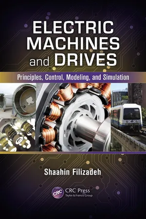
Electric Machines and Drives
Principles, Control, Modeling, and Simulation
- Shaahin Filizadeh(Author)
- 2013(Publication Date)
- CRC Press(Publisher)
1 1 Physics of Electric Machines 1.1 Introduction Electric machines are devices used for energy conversion, mostly between mechanical and electrical forms. An Electric Motor is a machine that con- verts the electrical energy given to it as input to mechanical energy output; a generator does the reverse by producing electrical energy from mechanical energy input. Study of electric machines, therefore, requires knowledge and understanding of the principles of energy conversion. Electric machines come in a wide variety of forms and sizes and are used in markedly different ways and applications. Consider, on the one hand, a small Electric Motor that rotates and precisely positions a compact disk in a CD drive and, on the other hand, a massive generator in a power plant that is driven by a turbine and generates large amounts of electricity. Despite such apparent differences in scale and application, all electric machines operate on the same underlying principles and share a simple backbone, which is a magnetic medium that links the electrical and mechanical ends of a machine. Apart from its function of facilitating generation and directing magnetic flux to link machine windings, an electromagnetic medium also enables and facilitates the conversion and flow of energy between the two ends of a rotat- ing electric machine, that is, its electrical and mechanical ends. Proper study of a rotating electric machine will therefore entail consideration of its mag- netic structure and its role in the process of energy conversion. Although the study of electromagnetic systems is often associated with vector calculus of Maxwell’s equations, it is indeed possible to describe and understand the behavior of electric machines in simple terms without recourse to compli- cated mathematics. The intention of this chapter is to establish a foundation for understanding the operation of rotating electric machines using simple laws of physics. No longer available |Learn more
- (Author)
- 2014(Publication Date)
- Learning Press(Publisher)
________________________ WORLD TECHNOLOGIES ________________________ Chapter- 4 Electric Motor Electric Motors ________________________ WORLD TECHNOLOGIES ________________________ An Electric Motor is a type of machine that converts electrical energy into mechanical energy. Electric Motors operate through interacting magnetic fields and current-carrying conductors to generate force, although a few use electrostatic forces. The reverse process, producing electrical energy from mechanical energy, is accomplished by an alternator, generator or dynamo. Many types of Electric Motors can be run as generators, and vice versa. For example a starter/generator for a gas turbine or Traction motors used on vehicles often perform both tasks. Electric Motors are found in applications as diverse as industrial fans, blowers and pumps, machine tools, household appliances, power tools, and disk drives. They may be powered by direct current (e.g., a battery powered portable device or motor vehicle), or by alternating current from a central electrical distribution grid. The smallest motors may be found in electric wristwatches. Medium-size motors of highly standardized dimen-sions and characteristics provide convenient mechanical power for industrial uses. The very largest Electric Motors are used for propulsion of large ships, and for such purposes as pipeline compressors, with ratings in the millions of watts. Electric Motors may be classified by the source of electric power, by their internal construction, by their appli-cation, or by the type of motion they give. The physical principle of production of mechanical force by the interactions of an electric current and a magnetic field was known as early as 1821. Electric Motors of increasing efficiency were constructed throughout the 19th century, but commercial exploitation of Electric Motors on a large scale required efficient electrical generators and electrical distribution networks.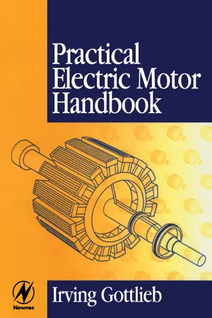 eBook - PDF
- Irving Gottlieb(Author)
- 1997(Publication Date)
- Newnes(Publisher)
In a Electric Motor generalities 7 Fig. 1.6 Motor action exerted on current-carrying conductor in a magnetic field. Endowing magnetic lines of force with the elastic property of rubber- bands, enables one to visualize the motion imparted to a current-carrying conductor. The interaction of the magnetic fields as shown is found in vir- tually all Electric Motors. Downward motion of the conductor would occur if either (not both) the current direction or the magnetic poles were reversed. Note: Conventional current-flow is used in this book. general, but inviolate way, it tells us that 'any change in magnetic flux linkage is accompanied by effects opposing the change'. The electrlc motor as an energy converter At the very outset, we should concern ourselves with what Electric Motors do. A popular but erroneous notion is that Electric Motors create or produce mechanical energy. Mechanical energy is definitely not created; yes, it may be said to be produced at the shaft of the motor, but this is, at best, only a partial answer. We must point out that this mechanical energy comes at the expense of some other form of energy. The simple and true fact of the matter is that the Electric Motor (and the electric generator, as well) is an energy converter. More specifically, the motor converts electrical energy into mechanical energy. In so doing, it is never 100% efficient-in the overall budget of energy availability, there are always inevitable energy losses. These losses may manifest themselves as still other forms of energy, such as heat, light, sound, friction, radiation, etc. Energy, itself is the capability of doing work. In the practical world, it would be well to say that available energy represents the capability of doing usefulwork. Because of nature's previous activities, most of the useful energy 8 Practical Electric Motor Handbook ,, , . . . . sources stem from various chemical, gravitational, and nuclear arrangements of planetary matter. No longer available |Learn more
- (Author)
- 2014(Publication Date)
- Orange Apple(Publisher)
________________________ WORLD TECHNOLOGIES ________________________ Chapter 10 Electric Motor Electric Motors ________________________ WORLD TECHNOLOGIES ________________________ An Electric Motor converts electrical energy into mechanical energy. Most Electric Motors operate through interacting magnetic fields and current-carrying conductors to generate force, although electrostatic motors use electrostatic forces. The reverse process, producing electrical energy from mechanical energy, is done by generators such as an alternator or a dynamo. Many types of Electric Motors can be run as generators, and vice versa. For example a starter/generator for a gas turbine, or traction motors used on vehicles, often perform both tasks. Electric Motors and generators are commonly referred to as electric machines. Electric Motors are found in applications as diverse as industrial fans, blowers and pumps, machine tools, household appliances, power tools, and disk drives. They may be powered by direct current (e.g., a battery powered portable device or motor vehicle), or by alternating current from a central electrical distribution grid. The smallest motors may be found in electric wristwatches. Medium-size motors of highly standardized dimensions and characteristics provide convenient mechanical power for industrial uses. The very largest Electric Motors are used for propulsion of ships, pipeline compressors, and water pumps with ratings in the millions of watts. Electric Motors may be classified by the source of electric power, by their internal construction, by their application, or by the type of motion they give. The physical principle of production of mechanical force by the interactions of an electric current and a magnetic field was known as early as 1821. No longer available |Learn more
- (Author)
- 2014(Publication Date)
- Academic Studio(Publisher)
____________________ WORLD TECHNOLOGIES ____________________ Chapter 1 Electric Motor Electric Motors ____________________ WORLD TECHNOLOGIES ____________________ An Electric Motor converts electrical energy into mechanical energy. Most Electric Motors operate through interacting magnetic fields and current-carrying conductors to generate force, although electrostatic motors use electrostatic forces. The reverse process, producing electrical energy from mechanical energy, is done by generators such as an alternator or a dynamo. Many types of Electric Motors can be run as generators, and vice versa. For example a starter/generator for a gas turbine, or traction motors used on vehicles, often perform both tasks. Electric Motors and generators are commonly referred to as electric machines. Electric Motors are found in applications as diverse as industrial fans, blowers and pumps, machine tools, household appliances, power tools, and disk drives. They may be powered by direct current (e.g., a battery powered portable device or motor vehicle), or by alternating current from a central electrical distribution grid. The smallest motors may be found in electric wristwatches. Medium-size motors of highly standardized dimensions and characteristics provide convenient mechanical power for industrial uses. The very largest Electric Motors are used for propulsion of ships, pipeline compressors, and water pumps with ratings in the millions of watts. Electric Motors may be classified by the source of electric power, by their internal construction, by their application, or by the type of motion they give. The physical principle of production of mechanical force by the interactions of an electric current and a magnetic field was known as early as 1821. Electric Motors of increasing efficiency were constructed throughout the 19th century, but commercial exploitation of Electric Motors on a large scale required efficient electrical generators and electrical distribution networks. No longer available |Learn more
- (Author)
- 2014(Publication Date)
- Orange Apple(Publisher)
________________________ WORLD TECHNOLOGIES ________________________ Chapter 1 Electric Motor Electric Motors ________________________ WORLD TECHNOLOGIES ________________________ An Electric Motor converts electrical energy into mechanical energy. Most Electric Motors operate through interacting magnetic fields and current-carrying conductors to generate force, although electrostatic motors use electrostatic forces. The reverse process, producing electrical energy from mechanical energy, is done by generators such as an alternator or a dynamo. Many types of Electric Motors can be run as generators, and vice versa. For example a starter/generator for a gas turbine, or traction motors used on vehicles, often perform both tasks. Electric Motors and generators are commonly referred to as electric machines. Electric Motors are found in applications as diverse as industrial fans, blowers and pumps, machine tools, household appliances, power tools, and disk drives. They may be powered by direct current (e.g., a battery powered portable device or motor vehicle), or by alternating current from a central electrical distribution grid. The smallest motors may be found in electric wristwatches. Medium-size motors of highly standardized dimens-ions and characteristics provide convenient mechanical power for industrial uses. The very largest Electric Motors are used for propulsion of ships, pipeline compressors, and water pumps with ratings in the millions of watts. Electric Motors may be classified by the source of electric power, by their internal construction, by their application, or by the type of motion they give. The physical principle of production of mechanical force by the interactions of an electric current and a magnetic field was known as early as 1821. No longer available |Learn more
- (Author)
- 2014(Publication Date)
- Orange Apple(Publisher)
________________________ WORLD TECHNOLOGIES ________________________ Chapter 5 Electric Motor Electric Motors ________________________ WORLD TECHNOLOGIES ________________________ An Electric Motor converts electrical energy into mechanical energy. Most Electric Motors operate through interacting magnetic fields and current-carrying conductors to generate force, although electrostatic motors use electrostatic forces. The reverse process, producing electrical energy from mechanical energy, is done by generators such as an alternator or a dynamo. Many types of Electric Motors can be run as generators, and vice versa. For example a starter/generator for a gas turbine, or traction motors used on vehicles, often perform both tasks. Electric Motors and generators are commonly referred to as electric machines. Electric Motors are found in applications as diverse as industrial fans, blowers and pumps, machine tools, household appliances, power tools, and disk drives. They may be powered by direct current (e.g., a battery powered portable device or motor vehicle), or by alternating current from a central electrical distribution grid. The smallest motors may be found in electric wristwatches. Medium-size motors of highly standardized dimensions and characteristics provide convenient mechanical power for industrial uses. The very largest Electric Motors are used for propulsion of ships, pipeline compressors, and water pumps with ratings in the millions of watts. Electric Motors may be classified by the source of electric power, by their internal construction, by their application, or by the type of motion they give. The physical principle of production of mechanical force by the interactions of an electric current and a magnetic field was known as early as 1821.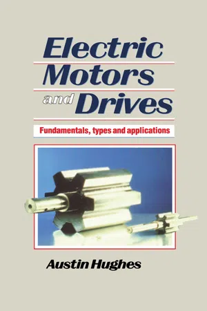 eBook - PDF
Electric Motors and Drives
Fundamentals, types and applications
- Austin Hughes(Author)
- 2013(Publication Date)
- Newnes(Publisher)
7 Electric MotorS INTRODUCTION Electric Motors are so much a part of everyday life that we seldom give them a second thought. When we switch on an electric drill, for example, we expect it to run rapidly up to the correct speed, and we don't question how it knows what speed to run at, nor how it is that once enough energy has been drawn from the supply to bring it up to speed, the power drawn falls to a very low level. When we put the drill to work it draws more power, and when we finish the power drawn from the mains reduces automatically, without inter-vention on our part. The humble motor, consisting of nothing more than an arrangement of copper coils and steel laminations, is clearly rather a clever energy converter, which warrants serious con-sideration. By gaining a basic understanding of how the motor works, we will be able to appreciate its potential and its limitations, and (in later chapters) see how its already remarkable performance can be even further improved by the addition of external controls. This chapter deals with the basic mechanisms of motor operation, so readers who are already familiar with such matters as magnetic flux, magnetic and electric circuits, torque, and motional e.m.f. can probably afford to skip most 2 Electric Motors and Drives PRODUCING ROTATION Nearly all motors exploit the force which is exerted on a current-carrying conductor placed in a magnetic field. The force can be demonstrated by placing a bar magnet near a wire carrying current, but anyone who tries the experiment will probably be disappointed to discover how feeble the force is, and will doubtless be left wondering how such an unpromising effect can be used to make effective motors. We shall see that in order to make the most of the mechan-ism, we need to arrange for there to be a very strong magnetic field, and for it to interact with many conductors, each carry-ing as much current as possible.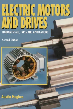 eBook - PDF
Electric Motors and Drives
Fundamentals, Types and Applications
- Austin Hughes(Author)
- 2013(Publication Date)
- Newnes(Publisher)
Our primitive set-up is simply a machine which is equally at home acting as motor or generator. A further important point to note is that the mechanical power (the first term on the right hand side of equation 1.20) is simply the motional e.m.f. multiplied by the current. This result is again universally applicable, and easily remembered. We may sometimes have to be a bit careful if the e.m.f. and the current are not simple d.c. quantities, but the basic idea will always hold good. Motoring condition Motoring implies that the conductor is moving in the same direction as the electromagnetic force (BIl), and at a speed such that the back e.m.f. (BLv) is less than the applied voltage V. In the discussion so far, we have assumed that the applied voltage is adjusted so that the current is kept constant. This was a helpful approach to take in order to derive the steady-state power relationships, but is seldom typical of normal operation. We therefore turn to how the moving conductor will behave under conditions where the applied voltage Vis constant, since this corresponds more closely with operation of a real motor. Behaviour with no mechanical load If we begin with the conductor stationary when the voltage Vis first applied, the current will immediately rise to a value of V/R, since there is no motional e.m.f. and the only thing which limits the current is the resistance. (Strictly we should allow for the effect of inductance in delaying the rise of current, but we choose to ignore it here in the interests of simplicity.) The current will be large, and a high force will therefore be 28 Electric Motors and Drives Figure 1.13 Dynamic behaviour of the elementary motor with no mechanical load We note that in this idealised situation (in which there is no load applied, and no friction forces), the conductor will continue to travel at a constant speed, because with no nett force acting on it there is no acceleration.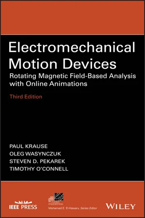 eBook - PDF
Electromechanical Motion Devices
Rotating Magnetic Field-Based Analysis with Online Animations
- Paul C. Krause, Oleg Wasynczuk, Steven D. Pekarek, Timothy O'Connell(Authors)
- 2020(Publication Date)
- Wiley-IEEE Press(Publisher)
CHAPTER 2 ELECTROMECHANICAL ENERGY CONVERSION 2.1 INTRODUCTION The theory of electromechanical energy conversion is the cornerstone for the anal- ysis of electrical motion devices. This theory allows us to express the electromag- netic force or torque in terms of device variables such as the currents and the displacement of the mechanical system. Since numerous types of electromechan- ical devices are used in motion systems, it is desirable to establish methods of anal- ysis that may be applied to a variety of electromechanical devices rather than just to electric machines. Therefore, the theory of electromechanical energy conversion is set forth in considerable detail for the purpose of providing a background sufficient to analyze electromechanical systems other than just those treated in this text. The first part of this chapter is devoted to establishing analytically the relationships that can be used to express the electromagnetic force or torque. Although one may pre- fer to perform a separate derivation for each device because it is instructive to do so, a general set of formulas are given in tabular form that are applicable to a variety of electromechanical systems with a single mechanical input. Once the theory of electromechanical energy conversion is established, a detailed analysis of the elementary electromagnet, which was introduced in Chapter 1, is performed with computer traces included to demonstrate its dynamic performance related to changes in the applied voltage and the external mechanical force. In the final sections, the expressions for the electromagnetic torque are developed for the elementary single-phase reluctance machine and for windings in relative motion. Brief discussions are given of several steady-state modes of operation of these devices, which help to illustrate, in an elementary form, the posi- tioning of stepper motors and the operation of synchronous motors.
Index pages curate the most relevant extracts from our library of academic textbooks. They’ve been created using an in-house natural language model (NLM), each adding context and meaning to key research topics.