Physics
Electrical Power
Electrical power is the rate at which electrical energy is transferred by an electric circuit. It is measured in watts and is the product of voltage and current in a circuit. In practical terms, electrical power is the amount of energy consumed or produced per unit of time.
Written by Perlego with AI-assistance
Related key terms
1 of 5
12 Key excerpts on "Electrical Power"
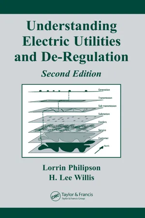
- H. Lee Willis, Lorrin Philipson(Authors)
- 2018(Publication Date)
- CRC Press(Publisher)
103 4 Electric Power 4.1 INTRODUCTION Electric power is a natural physical phenomenon, a fundamental type of energy which mankind has learned to create and control for its benefit. Electricity is always energy produced by converting some other form of energy (heat, mechanical motion, solar light, or moving wind, etc.) into electric power. Electricity has two advantages over other forms of energy that have led to its wide popularity. First, it is flexible : it can be transformed into heat, light, mechanical motion, radio signals, television images, and stereo sound. Second, it is very controllable : it can be turned on and off in a millionth of a second, and metered out precisely, from an amount so little that it would hardly move one grain of sand a tenth of a millimeter, to quantities that can power entire nations. This chapter is a basic “layman’s tutorial” on electricity, electric power, and the basics of Electrical Power engineering. It discusses electricity, electric power, and some of the fundamental concepts used in electric utility systems at an introductory level. Occasionally it glosses over messy details if they are not needed to explain the fundamental “big picture.” Persons with an electric utility company who do not have an engineering background may find it useful in understanding the basics of their company’s product. Engineers and others who know power may find it useful in helping explain basic power concepts to those new to the field and for preparing non-technical presentations to community groups, etc. It begins with a discussion of the basic concepts of voltage, current, power, and electric power flow in Section 4.2. Section 4.3 then discusses some of the characteristics of electric power that most shape or constrain its use. 104 Chapter 4 4.2 VOLTAGE, CURRENT, AND POWER Electricity has two fundamental components, th e current , or amount of electrical flow, and the voltage , or electrical pressure pushing the electric flow.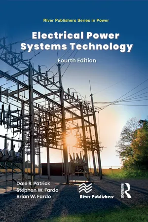 eBook - ePub
- Dale R. Patrick, Stephen W. Fardo, Brian W. Fardo(Authors)
- 2022(Publication Date)
- River Publishers(Publisher)
which the work is done. For instance, Electrical Power is the rate at which work is done as electrical current flows through a wire. Mechanical power is the rate at which work is done as an object is moved against opposition over a certain distance. Power is either the rate of production of energy or the rate of use of energy. The watt is the unit of measurement of power.Sample Problem: Power
Power is the time rate of doing work, which is expressed as follows:p =W t,where P = power in watts, W = work done in joules, and t = time taken to do the work in seconds.Given: An electric motor is used to move an object along a conveyance or line. The object has a mass of 150 kg and is moved 28 m in 8 s. Find: The power developed by the motor in watts and horsepower units. Solution:F o r c e( F )= 9.8 × m a s s= 9.8 × 150 k gF = 1470 n e w t o n sW o r k( W )= F × d= 1470 × 28 mW = 41 , 160 j o u l e sP o w e r( P )= W / t= 41 , 160 / 8P = 5145 w a t t sH o r s e p o w e r =Psin c e7461 h o r s e p o w e r = 746 Wh p = 5145 / 746 = 6.9 h pElectrical Power System
A block diagram of the Electrical Power systems model used in this textbook is shown in Figure 2-4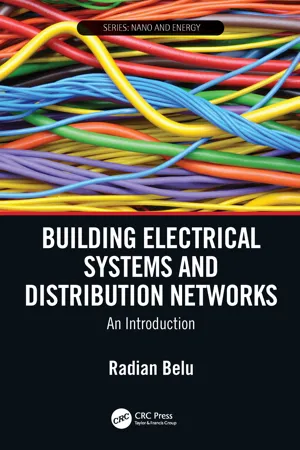 eBook - ePub
Building Electrical Systems and Distribution Networks
An Introduction
- Radian Belu(Author)
- 2020(Publication Date)
- CRC Press(Publisher)
2 Review of Electric Circuits and Power System Basics2.1INTRODUCTION TO ELECTRIC CIRCUIT REVIEW
The study of electric circuits covers the fundamental phenomenon of electric charge carrier flows. The fundamental quantities of current and voltage are used to describe how rapidly charged particles move in a circuit and in what way they do so in the circuit. Current is sometimes referred to as the “through” quantity and voltage as the “across” quantity. In a physical context, current is the flow of electric charge through a component or apparatus, whereas voltage is the potential difference between two points in a circuit. Current flows from high potential to low potential. In particular, we define the current, i(t), flowing in a component or apparatus as the amount of charge passing through that component or apparatus per unit of time. Denoting charge by q(t), we may write current i(t) as:i ( t ) =d q ( t )d t(2.1) Two other important quantities frequently used to describe physical systems are power and energy. If a small quantity of electric charge Δq is displaced from a point A to a point B, then the change in its potential energy, or the work done, is equal to V·Δq, where V is the voltage between A and B. The amount of work done per unit of time, the time rate, is called power, and is usually denoted by P, defined as:P =limΔ t → 0= VV ⋅ Δ qΔ td qd t(2.2) Current unit is the ampere (A), for the voltage is volt (V), for the energy is joule (J), and for the power is watt (W). Prefixes are often used to emphasize the significant figures when these magnitudes are too large or too small. Common engineering prefixes and their corresponding multipliers are given in Table 2.1 eBook - ePub
- Zeki Uğurata Kocabiyikoğlu(Author)
- 2020(Publication Date)
- CRC Press(Publisher)
1 Basic Principles of Energy, Power and Electrical Power Systems1.1 Physical Foundations of Energy and Power
1.1.1 Energy
Here, we shall provide a reminder about- what energy is
- how it changes
- how electrical energy is obtained.
Energy is defined as the “capacity of a system to do work”. The most common unit used for energy is joule, abbreviated J. Electric utilities bill the energy in kilowatt hours (kWh). A kWh represents “one kW being used for one hour”, and it equals 3.6 MJ of energy. Energy can exist in many forms like heat, light, sound, mechanical, and electrical. It cannot be consumed but can be converted from one form to another. This is the law of “conservation of energy” described in the “first law of thermodynamics”. Whenever energy changes from one form to another, some of it is lost as heat. This is because energy transformations are not energywise reversible. Heat is a disorderly form of energy. On the other hand, electrical energy, kinetic energy, and potential energy are orderly forms of energy.Orderly forms of energy can easily be converted to heat. For example, electrical energy can be easily converted to heat by making a current flow in a resistor or by dropping a stone from a hill onto a hard surface and converting partially its kinetic energy to heat. On the other hand, transforming heat into electrical energy is much more difficult.The second law of thermodynamics says that “nature has a tendency towards disordered forms of energy”. This means that converting heat to electricity will not be as efficient as converting electricity to heat. About 60% of the heat energy input to power plants is lost as waste. Energy can be in the form of “kinetic energy” as in the case of a truck travelling down the hill, or it can be in the form of “potential energy” as in the case of a skier standing at the top of a hill (Figure 1.1 eBook - ePub
Electrical Engineering
Fundamentals
- Viktor Hacker, Christof Sumereder(Authors)
- 2020(Publication Date)
- De Gruyter Oldenbourg(Publisher)
B have to be fulfilled.Figure 1.17: Superconducting surface.1.11 Energy and Electrical Power
Electrical energy is provided by the combination of electric current and electric potential in an electrical circuit. The mechanical workW = ∫is comparable to electrical work done on a charged particle by an electric field.F ⃗⋅ ds ⃗If the force (F ) is used to lift an object by the distance (s), mechanical work is carried out. The object now has higher energy content by that amount (potential energy). This energy can perform work by e.g. letting the object drop.Electric energy the following applies:W = Q ⋅ V = V ⋅ I ⋅ tV Voltage in VI Current in At Time in sQ Electric charge in AsW Electrical work/energy in WsThe electric charge represents the product of current I multiplied by time (Q = I ⋅ t ). Therefore, the following applies:W =⋅ t = P ⋅ tPV ⋅ I⏟P Power in WThe work performed per time unit is called power P.P =W tWith direct current, the electric power P that is transformed in an electric load is the result of the voltage V multiplied by the current I :P = V ⋅ IPower is one of the most important parameters for electrical machines and devices. By insertion of the Ohm’s law, the equation can be transformed to:P = Wor also:Power hyperbola
All V-I pairs of values that lead to the same power, e.g.P = 2 W eBook - PDF
Physics of Electronic Materials
Principles and Applications
- Jørgen Rammer(Author)
- 2017(Publication Date)
- Cambridge University Press(Publisher)
Work is done by the electric field on each of the electrons and their average energy is changed as dictated by Newton’s equation: force times particle distance moved, i.e. the amount of work done on each electron per unit time is the force times the drift velocity, Eq. ( 4.117 ) (recall the resistor discussion in Section 4.9 ). In a small time interval, t , by definition of current, charge q = I t is transported through any cross-section of the resistor. In each cross-sectional volume, charge q enters and leaves, and the total work done by the electric field on the electrons in the component equals that of the charge q being transported in time interval t through the length of the component. Since the line integral of the electric field through the component equals the potential difference between its terminals, the voltage V , the work done is W = qV = I tV . The work provided by the voltage across the component is thus dissipated at the rate P = W / t = ˙ W = IV . Heating of a component increases its temperature, and the thermal agitation of the ionic lattice increases electron scattering and thereby its resistance as a 104 Electric Circuit Theory function of temperature. The ever-present heating in electric circuits is thus a nuisance that has to be countered by cooling, such as for example for computers and servers. The above power dissipation argument is quite general even when current is due to both positive and negative charge carriers. When an electric current, I , is flowing through a device, the work performed per unit time, the electric power, is P = ˙ W = IV , (5.9) the power equals current multiplied by voltage. In other words, when charge per unit time, I , is transported between two terminals of voltage difference V , the voltage provides the electric power IV to the device between the terminals. The unit of power is called the watt (W), 1 W equaling one joule per second (W = J/s). eBook - PDF
- Michael Brumbach(Author)
- 2016(Publication Date)
- Cengage Learning EMEA(Publisher)
28 Electrical Power and Energy O B J E C T I V E S After studying this chapter, the student will be able to: ■ Define the terms relating to Electrical Power and energy. ■ Calculate the power necessary to perform various electrical jobs. ■ Calculate the amount of electrical energy required to perform various electrical jobs. ■ Determine the horsepower necessary to drive various machines. ■ Calculate the efficiency of electrical equipment. ■ Calculate the cost of operating electrical equipment. C H A P T E R 3 Copyright 2017 Cengage Learning. All Rights Reserved. May not be copied, scanned, or duplicated, in whole or in part. Due to electronic rights, some third party content may be suppressed from the eBook and/or eChapter(s). Editorial review has deemed that any suppressed content does not materially affect the overall learning experience. Cengage Learning reserves the right to remove additional content at any time if subsequent rights restrictions require it. Electrical Power AND ENERGY 29 1 50,000 3 10 2 4 5 5 100,000 ft 1b/mi n hp 5 ft 1b/min 33,000 hp 5 100,000 33,000 hp 5 3 Electric Power Electric power is measured in watts (W) or kilo-watts (kW). One thousand watts equal one kilowatt. It is relatively simple to convert from mechanical power to Electrical Power: 1 horsepower is equal to 746 watts. (One watt per second equals one joule.) One watt of power is developed when one volt forces one ampere through a circuit. This can be ex-pressed mathematically by the formula P 5 IE a I 5 P E or E 5 P I b (Eq. 3.2) where P 5 power, in watts (W) I 5 current, in amperes (A) E 5 electrical pressure, in volts (V) As was the situation with Ohm’s law, if you have difficulty manipulating these three power law formulas, a simple device can help. This device is called the power law triangle and is illustrated in Figure 3–1. eBook - ePub
- S. Bobby Rauf(Author)
- 2020(Publication Date)
- CRC Press(Publisher)
1 Fundamental Electrical Engineering Concepts and PrinciplesIntroduction
In this first chapter of the Electrical Engineering Fundamentals text, we will explore fundamental electrical engineering terms, concepts, principles, and analytical techniques and impart knowledge that is considered elemental in the discipline of electrical engineering. Readers who invest time and effort in studying this text are likely to do so for the key purpose of gaining an introduction into the field of electricity. In this chapter, we will lay the foundations in the electrical engineering realm by covering basic electrical engineering terms, concepts, and principles, without the understanding of which, discussion and study of terms that bear important practical significance, such as power factor, real power, reactive power, apparent power, and load factor, would be untenable.Most of the material in this chapter pertains to DC, or direct current, electricity. However, some entities discussed in this chapter such as capacitive reactance, inductive reactance, and impedance are fundamentally entrenched in the AC, alternating current, realm.This text affirms that electrical engineering is rooted in the field of physics and chemistry. Physics, chemistry, and electrical engineering, as most other subject matters in science, depend on empirical proof of principles and theories. Empirical analysis and verification require tools and instruments for measurement of various parameters and entities. Hence, after gaining a better understanding of the basic electrical concepts, we will conclude this chapter with an introduction to three of the most common and basic electrical instruments, namely, multi-meter, clamp-on ammeter, and a scope meter or oscilloscope.Voltage or EMF (Electromotive Force)
Voltage can be defined as a “force” that moves or pushes electrically charged particles like electrons, holes, negatively charged ions, or positively charged ions by forming an electric field. The term “electromotive” force stems from the early recognition of electrical current as something that consisted, strictly, of the movement of “electrons.” Nowadays, however, with the more recent breakthroughs in the renewable and non-traditional Electrical Power generating methods and systems like microbial fuel cells and hydrocarbon fuel cells, Electrical Power is being harnessed, more and more, in the form of charged particles that may not be electrons. In batteries, such as those used in automobiles, as we will see in the batteries chapter, the flow of current driven by voltage potential difference consists not only of negatively charged electrons, e− , but also types of ions, including H+ and HSO4 − ions.1 eBook - PDF
- John D. Cutnell, Kenneth W. Johnson, David Young, Shane Stadler, Heath Jones, Matthew Collins, John Daicopoulos, Boris Blankleider(Authors)
- 2020(Publication Date)
- Wiley(Publisher)
Note that the positive (+) terminal of the battery is con- nected by a wire to the terminal labelled A on the device; likewise, the negative terminal (−) of the battery is connected to the B terminal. Thus, the battery maintains a constant poten- tial difference between the terminals A and B, with A being at the higher potential. When an amount of positive charge Δq moves from the higher potential (A) to the lower potential (B), its electric potential energy decreases. In accordance with equation 19.4, this decrease is (Δq)V, where V is the amount by which the electric potential at A exceeds that at B or, in other words, the voltage between the two points. Since the change in energy per unit time is the power P (equation 6.10b), the electric power associated with this change in energy is P = Change in energy Time interval = (Δq) V Δt = Δq Δt ⏟ ⏟ ⏟ Current I V CHAPTER 20 Electric circuits 543 The term Δq/Δt is the charge per unit time, or the current I in the device, according to equation 20.1. It follows, then, that the electric power is the product of the current and the voltage. Electric power When electric charge flows from point A to point B in a circuit, leading to a current I, and the voltage between the points is V, the electric power associated with this current and voltage is P = IV (20.6) SI unit of power: watt (W) Power is measured in watts, and equation 20.6 indicates that the product of an ampere and a volt is equal to a watt. When the charge moves through the device in figure 20.8, the charge loses electric potential energy. The principle of conservation of energy tells us that the decrease in potential energy must be accompanied by a transfer of energy to some other form (or forms). In a mobile phone, for example, the energy transferred appears as light energy (coming from the display screen), sound energy (emanating from the speaker), thermal energy (due to heating of the internal circuitry), and so on.
- S. Bobby Rauf(Author)
- 2021(Publication Date)
- River Publishers(Publisher)
Chapter 1 Electrical Engineering Basics and Direct CurrentIntroduction
In this chapter, we will explore the basics of electrical engineering terms, concepts, principles, and analytical techniques. Many readers who embark on investing time and effort in studying this text are likely to do so for the key purpose of gaining an introduction into the field of electricity. Many others, on the other hand, might be interested in refurbishing prior knowledge of electrical engineering terms, concepts, principles, and basic analytical techniques. Regardless of whether you belong to one of these two groups —or are simply in pursuit of electrical engineering at the intermediate or associate degree level — in this chapter we will lay the foundations in the electrical engineering realm by covering basic electrical engineering terms, concepts, and principles, without the understanding of which, discussion and study of terms that bear important practical significance, such as power factor, real power, reactive power, apparent power, load factor, etc. would not be feasible.Most of the material in this chapter pertains to DC, or Direct Current, electricity. However, some entities we will discuss in this chapter, such as capacitive reactance, inductive reactance, and impedance are fundamentally premised in the AC, Alternating Current, realm.Electrical engineering is largely rooted in the field of physics. Physics, and electrical engineering, as most other fields in science, depend on empirical proof of principles and theories. Empirical analysis and verification require measurement tools or instrumentation. So, after gaining a better understanding of the basic electrical concepts, we will conclude this chapter with an introduction to two of the most common and basic electrical instruments, i.e., multi-meter and clamp-on ammeter. No longer available |Learn more
Wiley Survival Guides in Engineering and Science
A Conceptual Introduction
- Alexandra von Meier(Author)
- 2006(Publication Date)
- Wiley-IEEE Press(Publisher)
Another conceivable application of superconductivity in power systems is superconducting magnetic energy storage (SMES). 1.1.6 Current When charge travels through a material, an electric current is said to flow. The current is quantified in terms of the number of electrons (or equivalent charge, in 7 In fact, conductivity is used as an indicator of water purity. Of course, it says nothing about the kind of ions present, only the amount. 8 The ionization trail is visible because, as the electrons return to their normal state, the balance of their energy is released in the form of light. 9 The first such material to be discovered was yttrium-barium-copper oxide, YBa 2 Cu 3 O 7 . 6 THE PHYSICS OF ELECTRICITY the case of ions) moving past a given point in the material in a certain period of time. In other words, current is a flow rate of charge. In this way, electric current is ana- logous to a flow rate of water (say, in gallons per minute) or natural gas (cubic feet per second). These analogies are also helpful in remembering the distinction between current and voltage. Voltage would be analogous to a height difference (say, between a water reservoir and the downhill end of a pipe), or to a pressure difference (between two ends of a gas pipeline). Intuitively, voltage is a measure of “how badly the stuff wants to get there,” and current is a measure of “how much stuff is actually going.” Current is conventionally denoted by the symbol I or i and is measured in units of amperes (A), often called “amps.” Since current represents a flow rate of charge, the units of current are equivalent to units of charge divided by units of time. Thus, one ampere equals one coulomb per second. A subject that often causes confusion is the “direction” in which current flows, though in practice, having an accurate picture of this is not all that important.
- John Bird(Author)
- 2013(Publication Date)
- Butterworth-Heinemann(Publisher)
The coulomb is defined as the quantity of electricity which flows past a given point in an electric circuit when a current 1 4 UNITS ASSOCIATED WITH BASIC ELECTRICAL QUANTITIES of one ampere is maintained for one second. Thus, charge, in coulombs Q = It where / is the current in amperes and t is the time in seconds. Problem 1. If a current of 5 A flows for 2 minutes, find the quantity of electricity transferred. Quantity of electricity Q - It coulombs. / = 5 A, t = 2 X 60 = 120 s, hence Q = 5 X 120 = 600 C 1.4 Work The unit of work or energy is the joule (J) where one joule is one newt on metre. The joule is defined as the work done or energy transferred when a force of one newton is exerted through a distance of one metre in the direction of the force. Thus work done on a body, in joules W=Fs where F is the force in newtons and s is the distance in metres moved by the body in the direction of the force. Energy is the capacity for doing work. 1.3 Force The unit of force is the newton (N) where one newton is one kilogram metre per second squared. The newton is defined as the force which, when applied to a mass of one kilogram, gives it an accel-eration of one metre per second squared. Thus, force, in newtons F = ma where m is the mass in kilograms and a is the accel-eration in metres per second squared. Gravi-tational force, or weight, is rag, where g = 9.81 m/s 2 . Problem 2. A mass of 5000 g is accelerated at 2 m/s 2 by a force. Determine the force needed. Force = mass X acceleration = 5 kg X 2 m/s 2 = 10 ^ ^ -= 10 N Problem 3. Find the force acting vertically downwards on a mass of 200 g attached to a wire. Mass = 200 g = 0.2 kg, and acceleration due to gravity, g = 9.81 m/s 2 . Force acting downwards = weight = mass X acceleration = 0.2 kg X 9.81 m/s 2 = 1.962 N 1.5 Power The unit of power is the watt ( W) where one watt is one joule per second. Power is defined as the rate of doing work or transferring energy.
Index pages curate the most relevant extracts from our library of academic textbooks. They’ve been created using an in-house natural language model (NLM), each adding context and meaning to key research topics.