Physics
Moment of Inertia
Moment of inertia is a measure of an object's resistance to changes in its rotation. It depends on the mass distribution of the object and the axis of rotation. The larger the moment of inertia, the more difficult it is to change the object's rotational motion.
Written by Perlego with AI-assistance
Related key terms
1 of 5
11 Key excerpts on "Moment of Inertia"
 eBook - PDF
- Stephen Lee(Author)
- 2014(Publication Date)
- CRC Press(Publisher)
‘Inertia’ is a word which is used to describe a resistance to change in motion; it is sometimes used in place of mass. The larger the mass, or inertia, of a particle, the greater the amount of energy required to change its motion. In the same way, the energy required to change rotational motion is greater for bodies with large moments of inertia. C p axis of rotation V p = r p θ . r p m p θ . DYNAMICS OF RIGID BODIES ROTATING ABOUT A FIXED AXIS 453 . is used rather than because it might vary with time. A wooden top has a Moment of Inertia of 2.4 10 5 kg m 2 about its axis. It starts spinning when a string wound round the spindle of the top is pulled with a constant force of 0.5 N. Assuming there is no loss of energy due to friction, find the angular speed attained by the top when the length of the string is 0.3 m. S OLUTION The work done in pulling the string is 0.5 0.3 0.15 J and, as no energy is lost in the process, this is equal to the gain in kinetic energy of the top. So the angular speed attained is rad s 1 , where 1 2 2.4 10 5 2 0.15 ⇒ 2 12 500. The angular speed is 112 rad s 1 correct to 3 significant figures. The kinetic energy of a rotating wheel So what is the kinetic energy of a rotating wheel? As usual when modelling mechanical systems, it is useful to begin with a simple case. The simplest model of a wheel is one in which the mass of the spokes or their equivalent is negligible and all the mass can be considered to be concentrated at the rim in a hoop or ring of radius r . Then every particle is the same distance, r , from the axle. The Moment of Inertia of the wheel about the axle is then I m p r 2 p m p r 2 Mr 2 where M is the total mass. When this wheel is rotating with angular speed . about an axis through its centre perpendicular to its plane, its kinetic energy is 1 2 I . 2 1 2 Mr 2 . 2 . The kinetic energy of a more complex wheel can be found when you know its Moment of Inertia, I , about the axis of rotation. No longer available |Learn more
- (Author)
- 2014(Publication Date)
- Library Press(Publisher)
The body consists of N point masses m i whose distances to the rotation axis are denoted r i . Each point mass will have the speed v i = ωr i , so that the total kinetic energy T of the body can be calculated as In this expression the quantity in parentheses is called the Moment of Inertia of the body (with respect to the specified axis of rotation). It is a purely geometric characteristic of the object, as it depends only on its shape and the position of the rotation axis. The Moment of Inertia is usually denoted with the capital letter I : It is worth emphasizing that r i here is the distance from a point towards the axis of rotation , not towards the origin. As such, the Moment of Inertia will be different when considering rotations about different axes. Similarly, the Moment of Inertia of a continuous solid body rotating about a known axis can be calculated by replacing the summation with the integral: where r is the radius vector of a point within the body, ρ ( r ) is the mass density at point r , and d ( r ) is the distance from point r to the axis of rotation. The integration goes over the volume V of the body. Properties The Moment of Inertia of the body is additive. That is, if a body can be decomposed (either physically or conceptually) into several constituent parts, then the Moment of Inertia of the whole body about a given axis is equal to the sum of moments of inertia of each part around the same axis. Basing just on the dimensional analysis, the Moment of Inertia must take the form I = c·M·L 2 , where M is the mass, L is the “size” of the body in the direction perpendicular to the axis of rotation, and c is a dimensionless inertial constant . Additionally, the length is called the radius of gyration of the body. eBook - ePub
- Michael M. Mansfield, Colm O'Sullivan(Authors)
- 2020(Publication Date)
- Wiley(Publisher)
Chapter 3 we noted that mass represents a measure of how a body responds to an applied force, in the sense that it proves more difficult to give a large mass a translational acceleration than it is to give a small mass the same acceleration. In the same sense Moment of Inertia represents a measure of how a rigid body responds to an applied torque; for example, it requires a larger torque to produce the same angular acceleration in a wheel of large radius than in a wheel of the same mass but of smaller radius.The SI unit for Moment of Inertia iskg m2.For problems based on the material presented in this section visit up.ucc.ie/7/ and follow the link to the problems.7.7 Calculation of moments of inertia: the parallel axis theorem
So far we have treated a rigid body as an assemblage of discrete particles. Alternatively we may wish to consider a rigid body as a continuous distribution of matter, in which case the body may be thought of as divided into a very large number of infinitesimal mass elements (The Moment of Inertia about a symmetry axis of a body which has a relatively simple geometrical shape can be determined without undue difficulty as demonstrated by the following examples.Δmin Figure 7.14 is one such element). The summations in Equations (7.10) and (7.11) are then replaced by integrals and the Moment of Inertia can be calculated by integrating over the whole body, that is , where r is the perpendicular distance from the element Δm to the axis. This is an example of a volume integral (Appendix A.12.4 ).For a continuous distribution of matter in a rigid body, the body may be thought of as comprising a very large number of mass elements ΔmFigure 7.14 eBook - ePub
Reading Physics
A Guide to Understanding Basic Classical Mechanics without Mathematical Expressions
- Jae Jun Kim, Ph.D.(Authors)
- 2023(Publication Date)
- Universal Publishers(Publisher)
Let us look at the colors. You might already have noticed that the items in light gray are ones that change as a function of time and the ones in gray are not. For instance, in a linear motion, the positions in the horizontal and vertical directions change, so they are colored gray. In a rotational motion, the size does not change, so it is colored gray. Given all that, here comes an important question. If angle is something that is going to change, but the distance and the mass are not, why not combine the ones that do not change together? Answer: That is exactly where we introduce the Moment of Inertia. In a rotational motion, the Moment of Inertia is not going to change as a function of time. In short, we can treat the Moment of Inertia just like we do mass in a linear motion.Remember that we do not always need to introduce the Moment of Inertia to describe rotational motion. It is just that introducing the quantity makes studying and understanding the rotational motion easier, so do so. We take the quantities that change as a function of time from the ones that do not change. When combining all the quantities that do not change, as colored in gray in Figure 33.1 , we end up with the Moment of Inertia in a rotational motion.How do we define the Moment of Inertia mathematically? It is mass multiplied by distance squared. Is that the end of the story? Probably not. For a test particle, it is as simple as that. If there is a point and if we are to describe its Moment of Inertia, that is all we need to understand. However, when calculating the size of the Moment of Inertia, we calculate the momentum of inertia for an individual piece of mass within the object and add them up together in the end, which is where we need to introduce calculus.For instance, the Moment of Inertia for a ring with respect to a line passing the center is just mass multiplied by the radius of the ring. However, when you do the same but for a solid sphere, an individual chunk of mass within the sphere has a different distance with respect to the center of the sphere, so we need to introduce calculus to calculate the total Moment of Inertia associated with the shape of the object; you do the same for any other object with a different shape.Figure 33.1: In a two-dimensional linear motion, we need two quantities in length and one in mass to describe its motion. In a rotational motion, what do we need instead?Figure 33.2: Imagine that we have a solid sphere that rotates with respect to an axis that passes through the center. The two small circles in the figure represent the two infinitesimally small pieces within the sphere. In terms of the displacement associated with the two small pieces per rotation of the sphere, the size of the displacement is going to be larger for the one that is farther from the axis, which is the one with the larger size arrow in light gray. Question: how do you accommodate for the difference in the distance to the rotational axis when calculating the size of the Moment of Inertia? We cannot simply assume that the Moment of Inertia is going to be simply the total mass times the radius squared. Why? All the small pieces shown in the figure have different sizes for distance.
- Raymond Serway, John Jewett(Authors)
- 2018(Publication Date)
- Cengage Learning EMEA(Publisher)
10.6 Calculation of Moments of Inertia The Moment of Inertia of a system of discrete particles can be calculated in a straightforward way with Equation 10.19. On the other hand, suppose we consider a continuous rigid object. We can evaluate its Moment of Inertia by imagining the Copyright 2019 Cengage Learning. All Rights Reserved. May not be copied, scanned, or duplicated, in whole or in part. Due to electronic rights, some third party content may be suppressed from the eBook and/or eChapter(s). Editorial review has deemed that any suppressed content does not materially affect the overall learning experience. Cengage Learning reserves the right to remove additional content at any time if subsequent rights restrictions require it. 264 Chapter 10 Rotation of a Rigid Object About a Fixed Axis object to be divided into many small elements, each of which has mass Dm i . We use the definition I 5 o i r i 2 Dm i and take the limit of this sum as Dm i S 0. In this limit, the sum becomes an integral over the volume of the object: I 5 lim Dm i S 0 o i r i 2 Dm i 5 # r 2 dm (10.20) It is usually easier to calculate moments of inertia in terms of the volume of the elements rather than their mass, and we can easily make that change by using Equation 1.1, r ; m/V, where r is the density of the object and V is its volume. From this equation, the mass of a small element is dm 5 r dV. Substituting this result into Equation 10.20 gives I 5 # rr 2 dV (10.21) If the object is homogeneous, r is constant and the integral can be evaluated for a known geometry. If r is not constant, its variation with position must be known to complete the integration. The density given by r 5 m/V sometimes is referred to as volumetric mass density because it represents mass per unit volume. Often we use other ways of express- ing density. For instance, when dealing with a sheet of uniform thickness t , we can define a surface mass density s 5 m/ A 5 rt , which represents mass per unit area.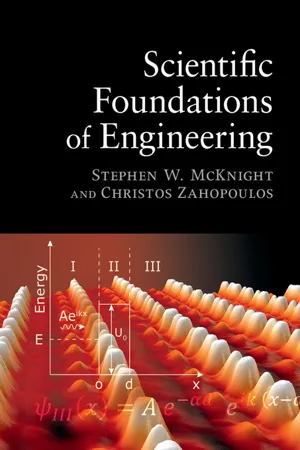 eBook - PDF
- Stephen McKnight, Christos Zahopoulos(Authors)
- 2015(Publication Date)
- Cambridge University Press(Publisher)
3.2 Moment of Inertia of a solid body To find the kinetic energy of a rotating solid body, we observe that the angular velocity of each particle of mass in the body is rotating at the same angular velocity ω (they each make one rotation – 2π radians – in the same time interval). We can define the rotational kinetic energy of the body to be KE ¼ 1 2 I ω 2 (3.4) if we define the Moment of Inertia by summing up mr 2 for each particle of the body I ¼ P i m i r i 2 ¼ Ð r 2 dm (3.5) where dm is an infinitesimal mass element and r is the distance of each element from the axis of rotation. For example, a uniform disk of mass M, thickness h, and radius R rotating around a perpendicular axis through the center of the disk, as shown in Figure 3.4, would have dm ¼ ρrhdθdr where ρ is the mass density, the total mass divided by the volume, ρ ¼ M/(πR 2 h). We find the Moment of Inertia of the disk around its axis by integrating over the whole disk, for dr from 0 to R and dθ from 0 to 2π as shown in Figure 3.4. I ¼ Ð r 2 dm ¼ ÐÐ r 2 ρhrdθdr ¼ ðð r 3 M πR 2 h h dθdr ¼ 2π R 4 4 M πR 2 h h ¼ M R 2 2 : 41 3.2 Moment of Inertia of a solid body The kinetic energy of a disk of mass 5 kg and radius 0.3 m rotating at 1 revolution per second is therefore KE ¼ 1 2 5 ð0:3Þ 2 2 ð2πÞ 2 ¼ 4:44 J. 3.3 Center of mass (COM) and parallel axis theorem If we know the Moment of Inertia of a solid object around an axis passing through its center of mass (COM), it is easy to find the Moment of Inertia around any axis parallel to the COM axis by the parallel axis theorem. The COM of a body or system of masses is the point that moves as if all the system’s mass were concentrated at that point and as if all external forces were concentrated there. eBook - ePub
- John Chiasson(Author)
- 2022(Publication Date)
- Wiley(Publisher)
5 Rigid Body Rotational Dynamics 5.1 Moment of Inertia The equation s of motion of a rigid body that is constrained to rotate about a fixed axis are reviewed here briefly. Consider the cylinder shown in Figure 5.1. Figure 5.1 Cylinder constrained to rotate about a fixed axis. The approach here is to obtain the equations of motion of the cylinder by first obtaining an expression for its kinetic energy. To do so, denote the angular speed of the cylinder by and the mass density of the material making up the cylinder by. Then consider the cylinder to be made up of a large number of small pieces of material where the th piece has mass This is illustrated in Figure 5.2. Each piece of mass is rotating at the same angular speed so that the linear speed of is where is the distance of from the axis of rotation. The kinetic energy of is given by Figure 5.2 Cylinder is considered to be made up of small masses The total kinetic energy is then Dividing the cylinder into f iner and finer pieces so that and, the sum becomes the integral The quantity is called the Moment of Inertia. Using the kinetic energy of the cylinder may now be written as Taking the axle radius to be zero, the Moment of Inertia of the cylinder (assuming the mass density is constant) is computed to be where is the total mass of the cylinder. 5.2 Newton's Law of Rotational Motion The kinetic energy is now used to derive a relationship between torque and angular acceleration. Recall from elementary mechanics that the work done on a mass by an external force equals the change in its kinetic energy eBook - PDF
Mathematical Methods and Physical Insights
An Integrated Approach
- Alec J. Schramm(Author)
- 2022(Publication Date)
- Cambridge University Press(Publisher)
(4.52) For a continuous body the mass elements m α are infinitesimal, and the sum becomes an integral over dm ≡ ρ dτ , where ρ ( r) is the mass density. Thus L = r × ( ω × r) ρ dτ, (4.53) where r = (x, y , z) is the position of the mass element ρ ( r )dτ . Now to identify the Moment of Inertia from within the angular momentum, we need to factor out ω from (4.53). This may appear impossible, given how the components of r and ω are entangled. Clever 38 4 INDEX ALGEBRA wielding of index notation, however, can do the trick. First apply the “BAC-CAB” identity (see inside front cover) to get L = r 2 ω − r( r · ω) ρ dτ, (4.54) which in index notation is L i = ⎛ ⎝ r 2 ω i − r i j r j ω j ⎞ ⎠ ρ dτ . (4.55) Using ω i = ∑ j ω j δ ij , we can factor out ω j ; then reversing the order of sum and integral yields L i = j δ ij r 2 − r i r j ω j ρ dτ = j ( r 2 δ ij − r i r j ) ρ dτ ω j ≡ j I ij ω j . (4.56) Thus we find the Moment of Inertia tensor I ij ≡ ( r 2 δ ij − r i r j ) ρ dτ, (4.57) which is completely independent of ω. So whereas the relation between linear momentum and velocity is determined by the mass of the object, the relation between angular momentum and angular velocity is regulated by the distribution of mass within the object. The Moment of Inertia quantifies this distribution. The utility of L i = ∑ j I ij ω j is that it distinguishes kinematics from dynamics: the Moment of Inertia tensor is a property of a rigid body, independent of its motion. So we see that the two definitions of angular momentum are in fact equivalent — but only if I is understood as a matrix, rather than a simple number proportional to mr 2 . Indeed, I ij ’s off-diagonal terms are what account for situations in which L is not parallel to ω . eBook - ePub
General Physics
Mechanics and Molecular Physics
- L D Landau, A. I. Akhiezer, E.M. Lifshitz(Authors)
- 2013(Publication Date)
- Pergamon(Publisher)
§12 that the kinetic energy of the system also falls into two corresponding parts. The “internal” motion is here represented by the rotation of the body about the centre of mass. The kinetic energy of a body moving in an arbitrary manner is thereforeThe suffix 0 signifies that the Moment of Inertia is taken about an axis through the centre of mass.E kin=1 2MV 2+1 2I 0Ω 2.[It should be noted, however, that in this form the result is of practical significance only if the axis of rotation has a constant direction in the body during the motion. Otherwise the Moment of Inertia has to be taken about different axes at different times, and is therefore no longer a constant.]Let us consider a rigid body rotating about an axis Z which does not pass through the centre of mass. The kinetic energy of this motion is , where I is the Moment of Inertia about the axis Z . On the other hand, we may regard this motion as consisting of a translational motion with the velocity V of the centre of mass and a rotation (with the same angular velocity Ω) about an axis through the centre of mass parallel to the axis Z . If the distance of the centre of mass from the axis Z is a , then its velocity V = a Ω. The kinetic energy of the body may therefore be written also asHenceE kin=1 2MV 2+1 2I 0Ω 2=1 2(M)a 2+I 0Ω 2.I =I 0+ Ma 2.This formula relates the Moment of Inertia of the body about any axis to its Moment of Inertia about a parallel axis through the centre of mass. It is evident that I is always greater than I 0 eBook - PDF
New Tertiary Mathematics
Further Applied Mathematics
- C. Plumpton, P. S. W. Macliwaine(Authors)
- 2016(Publication Date)
- Pergamon(Publisher)
Note that they may be applied in the forms: (1) The initial motion of the centre of mass ofa rigid body is the same as that of a particle of mass equal to the sum of the masses of the constituent particles acted upon by an impulse which is the vector sum of the external impulses acting on the particles. (2) Moment of impulse about the axis = change in angular momentum about the axis. The angular momentum (moment of momentum) is, by definition, Y/i x ^rfl = (Jjntr^e = I 0 è = I 0 w. Figure 10.12 represents a rigid body capable of rotation under gravity about a horizontal axis through a fixed point O. The body hanging freely at rest receives a horizontal blow B (i.e. it is acted upon by a horizontal impulse B) in the vertical plane containing G, its centre of mass. There will, in general, be an impulsive reaction of the axis on the body, denoted in the diagram by components X and Y in directions at right angles to and along GO. The line of action of B meets OG at N and ON = x. Then 376 DYNAMICS OF A RIGID BODY Ch. 10 §10:5 FIG. 10.12. (i) the moment of the impulse of B about the axis is equal to the change in the angular momentum about the axis of the rigid body ^Bx = M(k 2 + h 2 )œ, where M is the mass of the body, k its radius of gyration about a parallel axis through G, GO = h and œ is the angular speed of the body immediately after receiving the blow, and (ii) the initial motion of G is the same as that of a particle of mass M acted upon by a horizontal impulse B — X, a vertical impulse Y and starting to move horizontally with speed hœ =>B-X = Mhco, Y=0. Therefore eliminating £, M(k 2 + h 2 )w , f/t 2 + /i 2 1 X = — Mhœ = Mœl h >. It follows that X = 0 when x = (k 2 + h 2 )/h. In this case N is called the centre of percussion corresponding to the axis. The distance ON is the length of the E.S.P. for this axis, so that the centre of oscillation discussed in § 10:3 and the centre of percussion are the same point for a particular axis. eBook - ePub
- David J. Peery(Author)
- 2013(Publication Date)
- Dover Publications(Publisher)
as defined by Eqs. 4.7 and 4.8 is called the centroid of the area.FIG . 4.2.FIG . 4.3.4.2. Moment of Inertia. In considering inertia forces on rotating masses, it was found that the inertia forces on the elements of mass had a moment about the axis of rotation ofas shown in Fig. 4.3 . The term under the integral sign is defined as the Moment of Inertia of the mass about the z axis.Since the x and y coordinates of the elements are easier to tabulate than the radius, it is frequently convenient to use the relationr 2 = x 2 + y 2orAn area has no mass, and consequently no inertia, but it is customary to designate the following properties of an area as the moments of inertia of the area since they are similar to the moments of inertia of masses.The coordinates are shown in Fig. 4.4 . The polar Moment of Inertia of an area is defined as follows:From the relationship used in Eq. 4.10,FIG . 4.4.FIG . 4.5.It is frequently necessary to find the Moment of Inertia of an area about an axis when the Moment of Inertia about a parallel axis is known. The Moment of Inertia about the y axis shown in Fig. 4.5 is defined as follows:substituting the relation x = d + x ′ in Eq. 4.15,orwhere represents the distance of the centroid of the area from the y ′ axis, as defined in Eq. 4.7, represents the Moment of Inertia of the area about the y ′ axis, and A represents the total area. Equation 4.16 is simplified when the y ′ axis is through the centroid of the area, as shown in Fig. 4.6 .The term I c represents the Moment of Inertia of the area about a centroidal axis.FIG . 4.6.FIG . 4.7.The Moment of Inertia of a mass may be transferred to a parallel axis by a similar procedure to that used for the Moment of Inertia of an area. For the mass shown in Fig. 4.7 , the following relations apply where the centroidal axis C lies in the xz plane.substituting ,Since x
Index pages curate the most relevant extracts from our library of academic textbooks. They’ve been created using an in-house natural language model (NLM), each adding context and meaning to key research topics.