Physics
The Transfer of Energy by Electromagnetic Waves
"The Transfer of Energy by Electromagnetic Waves" refers to the process by which energy is transmitted through space via electromagnetic waves, such as light, radio waves, and microwaves. These waves consist of oscillating electric and magnetic fields that carry energy from one place to another without the need for a medium. This transfer of energy plays a crucial role in various natural and technological processes.
Written by Perlego with AI-assistance
Related key terms
1 of 5
9 Key excerpts on "The Transfer of Energy by Electromagnetic Waves"
 No longer available |Learn more
- (Author)
- 2014(Publication Date)
- Learning Press(Publisher)
________________________ WORLD TECHNOLOGIES ________________________ Chapter- 5 Electromagnetic Radiation Electromagnetic radiation (often abbreviated E-M radiation or EMR ) is a phenomenon that takes the form of self-propagating waves in a vacuum or in matter. It comprises electric and magnetic field components, which oscillate in phase perpendicular to each other and perpendicular to the direction of energy propagation. Electromagnetic radiation is classified into several types according to the frequency of its wave; these types include (in order of increasing frequency and decreasing wavelength): radio waves, microwaves, infrared radiation, visible light, ultraviolet radiation, X-rays and gamma rays. A small and somewhat variable window of frequencies is sensed by the eyes of various organisms; this is what is called the visible spectrum. The photon is the quantum of the electromagnetic interaction and the basic unit of light and all other forms of electromagnetic radiation and is also the force carrier for the electromagnetic force. EM radiation carries energy and momentum that may be imparted to matter with which it interacts. ________________________ WORLD TECHNOLOGIES ________________________ Physics Theory Shows three electromagnetic modes (blue, green and red) with a distance scale in micrometres along the x-axis. Electromagnetic waves were first postulated by James Clerk Maxwell and subsequently confirmed by Heinrich Hertz. Maxwell derived a wave form of the electric and magnetic equations, revealing the wave-like nature of electric and magnetic fields, and their symmetry. Because the speed of EM waves predicted by the wave equation coincided with the measured speed of light, Maxwell concluded that light itself is an EM wave. According to Maxwell's equations, a spatially-varying electric field generates a time-varying magnetic field and vice versa . No longer available |Learn more
- (Author)
- 2014(Publication Date)
- Academic Studio(Publisher)
________________________ WORLD TECHNOLOGIES ________________________ Chapter 5 Electromagnetic Radiation Electromagnetic radiation (often abbreviated E-M radiation or EMR ) is a pheno-menon that takes the form of self-propagating waves in a vacuum or in matter. It comprises electric and magnetic field components, which oscillate in phase perpendicular to each other and perpendicular to the direction of energy propagation. Electromagnetic radiation is classified into several types according to the frequency of its wave; these types include (in order of increasing frequency and decreasing wavelength): radio waves, microwaves, infrared radiation, visible light, ultraviolet radiation, X-rays and gamma rays. A small and somewhat variable window of frequencies is sensed by the eyes of various organisms; this is what is called the visible spectrum. The photon is the quantum of the electromagnetic interaction and the basic unit of light and all other forms of electromagnetic radiation and is also the force carrier for the electromagnetic force. EM radiation carries energy and momentum that may be imparted to matter with which it interacts. ________________________ WORLD TECHNOLOGIES ________________________ Physics Theory Shows three electromagnetic modes (blue, green and red) with a distance scale in micrometres along the x-axis. Electromagnetic waves were first postulated by James Clerk Maxwell and subsequently confirmed by Heinrich Hertz. Maxwell derived a wave form of the electric and magnetic equations, revealing the wave-like nature of electric and magnetic fields, and their symmetry. Because the speed of EM waves predicted by the wave equation coincided with the measured speed of light, Maxwell concluded that light itself is an EM wave. According to Maxwell's equations, a spatially-varying electric field generates a time-varying magnetic field and vice versa . No longer available |Learn more
- (Author)
- 2014(Publication Date)
- Library Press(Publisher)
____________________ WORLD TECHNOLOGIES ____________________ Chapter 6 Electromagnetic Radiation Electromagnetic radiation (often abbreviated E-M radiation or EMR ) is a phenomenon that takes the form of self-propagating waves in a vacuum or in matter. It comprises electric and magnetic field components, which oscillate in phase perpendicular to each other and perpendicular to the direction of energy propagation. Electromagnetic radiation is classified into several types according to the frequency of its wave; these types include (in order of increasing frequency and decreasing wavelength): radio waves, microwaves, infrared radiation, visible light, ultraviolet radiation, X-rays and gamma rays. A small and somewhat variable window of frequencies is sensed by the eyes of various organisms; this is what is called the visible spectrum. The photon is the quantum of the electromagnetic interaction and the basic unit of light and all other forms of electromagnetic radiation and is also the force carrier for the electromagnetic force. EM radiation carries energy and momentum that may be imparted to matter with which it interacts. ____________________ WORLD TECHNOLOGIES ____________________ Physics Theory Shows three electromagnetic modes (blue, green and red) with a distance scale in micrometres along the x-axis. Electromagnetic waves were first postulated by James Clerk Maxwell and subsequently confirmed by Heinrich Hertz. Maxwell derived a wave form of the electric and magnetic equations, revealing the wave-like nature of electric and magnetic fields, and their symmetry. Because the speed of EM waves predicted by the wave equation coincided with the measured speed of light, Maxwell concluded that light itself is an EM wave. According to Maxwell's equations, a spatially-varying electric field generates a time-varying magnetic field and vice versa . No longer available |Learn more
- (Author)
- 2014(Publication Date)
- Learning Press(Publisher)
____________________ WORLD TECHNOLOGIES ____________________ Chapter- 6 Electromagnetic Radiation Electromagnetic radiation (often abbreviated E-M radiation or EMR ) is a phenol-menon that takes the form of self-propagating waves in a vacuum or in matter. It comprises electric and magnetic field components, which oscillate in phase perpendicular to each other and perpendicular to the direction of energy propagation. Electromagnetic radiation is classified into several types according to the frequency of its wave; these types include (in order of increasing frequency and decreasing wavelength): radio waves, microwaves, infrared radiation, visible light, ultraviolet radiation, X-rays and gamma rays. A small and somewhat variable window of frequencies is sensed by the eyes of various organisms; this is what is called the visible spectrum. The photon is the quantum of the electromagnetic interaction and the basic unit of light and all other forms of electromagnetic radiation and is also the force carrier for the electromagnetic force. EM radiation carries energy and momentum that may be imparted to matter with which it interacts. ____________________ WORLD TECHNOLOGIES ____________________ Physics Theory Shows three electromagnetic modes (blue, green and red) with a distance scale in micrometres along the x-axis. Electromagnetic waves were first postulated by James Clerk Maxwell and subsequently confirmed by Heinrich Hertz. Maxwell derived a wave form of the electric and magnetic equations, revealing the wave-like nature of electric and magnetic fields, and their symmetry. Because the speed of EM waves predicted by the wave equation coincided with the measured speed of light, Maxwell concluded that light itself is an EM wave. According to Maxwell's equations, a spatially-varying electric field generates a time-varying magnetic field and vice versa . No longer available |Learn more
- (Author)
- 2014(Publication Date)
- Academic Studio(Publisher)
________________________ WORLD TECHNOLOGIES ________________________ Chapter 6 Electromagnetic Radiation Electromagnetic radiation (often abbreviated E-M radiation or EMR ) is a phenol-menon that takes the form of self-propagating waves in a vacuum or in matter. It comprises electric and magnetic field components, which oscillate in phase perpendicular to each other and perpendicular to the direction of energy propagation. Electromagnetic radiation is classified into several types according to the frequency of its wave; these types include (in order of increasing frequency and decreasing wavelength): radio waves, microwaves, infrared radiation, visible light, ultraviolet radiation, X-rays and gamma rays. A small and somewhat variable window of frequencies is sensed by the eyes of various organisms; this is what is called the visible spectrum. The photon is the quantum of the electromagnetic interaction and the basic unit of light and all other forms of electromagnetic radiation and is also the force carrier for the electromagnetic force. EM radiation carries energy and momentum that may be imparted to matter with which it interacts. ________________________ WORLD TECHNOLOGIES ________________________ Physics Theory Shows three electromagnetic modes (blue, green and red) with a distance scale in micrometres along the x-axis. Electromagnetic waves were first postulated by James Clerk Maxwell and subsequently confirmed by Heinrich Hertz. Maxwell derived a wave form of the electric and magnetic equations, revealing the wave-like nature of electric and magnetic fields, and their symmetry. Because the speed of EM waves predicted by the wave equation coincided with the measured speed of light, Maxwell concluded that light itself is an EM wave. According to Maxwell's equations, a spatially-varying electric field generates a time-varying magnetic field and vice versa . No longer available |Learn more
- (Author)
- 2014(Publication Date)
- College Publishing House(Publisher)
____________________ WORLD TECHNOLOGIES ____________________ Chapter 6 Wireless Energy Transfer An artist's depiction of a solar satellite, which could send energy wirelessly to a space vessel or planetary surface. Wireless energy transfer or Wireless Power is the process that takes place in any system where electrical energy is transmitted from a power source to an electrical load without interconnecting wires. Wireless transmission is useful in cases where instantaneous or continuous energy transfer is needed but interconnecting wires are inconvenient, hazardous, or impossible. Wireless energy transfer is different from wireless transmission of information, such as radio, where the signal-to-noise ratio (SNR) or the percentage of power received becomes ____________________ WORLD TECHNOLOGIES ____________________ critical only if it is too low to adequately recover the signal. With wireless power transmission, efficiency is the more important parameter. The most common form of wireless power transmission is carried out using induction, followed by electrodynamic induction. Other present-day technologies for wireless power include those based upon microwaves and lasers. History of wireless energy transfer • 1820 : André-Marie Ampère develops Ampere’s law showing that electric current produces a magnetic field. • 1831 : Michael Faraday develops Faraday’s law of induction describing the electromagnetic force induced in a conductor by a time-varying magnetic flux. • 1864 : James Clerk Maxwell synthesizes the previous observations, experiments and equations of electricity, magnetism and optics into a consistent theory and mathematically models the behavior of electromagnetic radiation. • 1888 : Heinrich Rudolf Hertz confirms the existence of electromagnetic radiation. Hertz’s apparatus for generating electromagnetic waves was a VHF or UHF radio wave spark gap transmitter.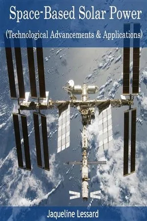 No longer available |Learn more
- (Author)
- 2014(Publication Date)
- College Publishing House(Publisher)
________________________ WORLD TECHNOLOGIES ________________________ Chapter-2 Wireless Energy Transfer An artist's depiction of a solar satellite, which could send energy wirelessly to a space vessel or planetary surface. Wireless energy transfer or Wireless Power is the process that takes place in any system where electrical energy is transmitted from a power source to an electrical load without interconnecting wires. Wireless transmission is useful in cases where instantaneous or continuous energy transfer is needed but interconnecting wires are inconvenient, hazardous, or impossible. Wireless energy transfer is different from wireless transmission of information, such as radio, where the signal-to-noise ratio (SNR) or the percentage of power received becomes critical only if it is too low to adequately recover the signal. With wireless power transmission, efficiency is the more important parameter. ________________________ WORLD TECHNOLOGIES ________________________ The most common form of wireless power transmission is carried out using induction, followed by electrodynamic induction. Other present-day technologies for wireless power include those based upon microwaves and lasers. History of wireless energy transfer • 1820 : André-Marie Ampère develops Ampere’s law showing that electric current produces a magnetic field. • 1831 : Michael Faraday develops Faraday’s law of induction describing the electromagnetic force induced in a conductor by a time-varying magnetic flux. • 1864 : James Clerk Maxwell synthesizes the previous observations, experiments and equations of electricity, magnetism and optics into a consistent theory and mathematically models the behavior of electromagnetic radiation. • 1888 : Heinrich Rudolf Hertz confirms the existence of electromagnetic radiation. Hertz’s apparatus for generating electromagnetic waves was a VHF or UHF radio wave spark gap transmitter. eBook - PDF
- John D. Cutnell, Kenneth W. Johnson, David Young, Shane Stadler, Heath Jones, Matthew Collins, John Daicopoulos, Boris Blankleider(Authors)
- 2020(Publication Date)
- Wiley(Publisher)
CHAPTER 24 Electromagnetic waves LEARNING OBJECTIVES After reading this module, you should be able to: 24.1 describe the nature of electromagnetic waves 24.2 calculate speed, frequency, and wavelength for electromagnetic waves 24.3 relate the speed of light to electromagnetic quantities 24.4 calculate energy, power, and intensity for electromagnetic waves 24.5 solve problems involving the Doppler effect for electromagnetic waves 24.6 solve polarisation problems using Malus’ law. INTRODUCTION Doppler radar provides crucial information to air traffic controllers, meteorologists and oceanographers. It is one of many devices that depend on the properties of electromagnetic waves, and how they transmit energy. 24.1 The nature of electromagnetic waves LEARNING OBJECTIVE 24.1 Describe the nature of electromagnetic waves. In section 13.3 we saw that energy is transported to us from the sun via a class of waves known as electromagnetic waves. This class includes the familiar visible, ultraviolet, and infrared waves. In sections 18.6, 21.1, and 21.2 we studied the concepts of electric and magnetic fields. It was the great Scottish physicist James Clerk Maxwell (1831–1879) who showed that these two fields fluctuating together can form a propagating electromagnetic wave. We will now bring together our knowledge of electric and magnetic fields in order to understand this important type of wave. Figure 24.1 illustrates one way to create an electromagnetic wave. The setup consists of two straight metal wires that are connected to the terminals of an ac generator and serve as an antenna. The potential difference between the terminals changes sinusoidally with time t and has a period T. Part a shows the instant t = 0 s, when there is no charge at the ends of either wire. Since there is no charge, there is no electric field at the point P just to the right of the antenna. As time passes, the top wire becomes positively charged and the bottom wire negatively charged. eBook - PDF
- John D. Cutnell, Kenneth W. Johnson, David Young, Shane Stadler(Authors)
- 2021(Publication Date)
- Wiley(Publisher)
Electromagnetic waves can travel through a vacuum or a material substance, since electric and magnetic fields can exist in either one. Electromagnetic waves can be produced in situations that do not involve a wire antenna. In general, any electric charge that is accelerating emits an electromagnetic wave, whether the charge is inside a wire or not. In an alternating current, an electron (a) t = 0 s P (b) t = T E P (c) P (d) P (e) t = T P + + + + – – – – 1 4 t = T 2 4 t = T 3 4 ANIMATED FIGURE 24.1 In each part of the drawing, the red arrow represents the electric field → E produced at point P by the oscillating charges on the antenna at the indicated time. The black arrows represent the electric fields created at earlier times. For simplicity, only the fields propagating to the right are shown. *The direction of the electric field can be obtained by imagining a positive test charge at P and determi- ning the direction in which it would be pushed because of the charges on the wires. B I P I FIGURE 24.2 The oscillating current I in the antenna wires creates a magnetic field → B at point P that is tangent to a circle centered on the wires. The field is directed as shown when the current is upward and is directed in the opposite direction when the current is downward. 24.1 The Nature of Electromagnetic Waves 761 y z x B E Direction of wave travel FIGURE 24.3 This picture shows the wave of the radiation field far from the antenna. Observe that → E and → B are perpendicular to each other, and both are perpendicular to the direction of travel. oscillates in simple harmonic motion along the length of the wire and is one example of an accelerating charge. All electromagnetic waves move through a vacuum at the same speed, and the symbol c is used to denote its value. This speed is called the speed of light in a vacuum and is c = 3.00 × 10 8 m/s.
Index pages curate the most relevant extracts from our library of academic textbooks. They’ve been created using an in-house natural language model (NLM), each adding context and meaning to key research topics.