Technology & Engineering
Gears
Gears are mechanical components with interlocking teeth that transmit power and motion between shafts. They are used to change the speed, torque, and direction of a power source, such as in vehicles, machinery, and clocks. Gears come in various types, including spur, helical, bevel, and worm gears, each designed for specific applications.
Written by Perlego with AI-assistance
7 Key excerpts on "Gears"
- eBook - ePub
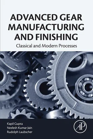
Advanced Gear Manufacturing and Finishing
Classical and Modern Processes
- Kapil Gupta, Neelesh Kumar Jain, Rolf Laubscher(Authors)
- 2017(Publication Date)
- Academic Press(Publisher)
Chapter 1 Introduction to Gear Engineering Abstract Gears are basic mechanical components used to transmit motion and/or power and are responsible for the smooth functioning of a significant number of machines, instruments, and equipments employed in most major industrial, scientific, and domestic applications. The purpose of this chapter is to present a basic introduction to Gears, their use, and manufacture. The chapter commences with an introduction to Gears along with a brief history. A classification scheme is then presented based on the gear-shaft axis orientation and corresponding gear types with their unique features and applications. The applicable gear terminology and nomenclature along with the most important gear materials, their properties, and application areas are presented next. The chapter is concluded with a brief introduction into gear manufacture comprising both conventional and advanced types along with the relevant finishing processes. Keywords Bevel gear; involute; gear hobbing; noncircular gear; spline; spur gear; worm wheel 1.1 Introduction and History of Gears 1.1.1 Introduction A gear is basically a toothed wheel that works in tandem with another gear (or Gears) to transmit power and/or motion to change speed and/or direction of motion. Dudley defined a gear as “a geometric shape that has teeth uniformly spaced around the circumference and is made to mesh its teeth with another gear” [1]. Slipping is a major problem during transmission of motion and power between two shafts by rope or belt drive and consequently may affect the precision and efficiency of the system adversely. This slipping phenomenon is largely avoided by means of gear drives. The compact layout, flexibility, high efficiency, and reliability are the most important features that make Gears and gear drives the first choice in many applications - eBook - PDF
- Harold Josephs, Ronald Huston(Authors)
- 2002(Publication Date)
- CRC Press(Publisher)
573 17 Mechanical Components: Gears 17.1 Introduction As with cams, Gears and gearing systems are fundamental mechanical components. Indeed, in the design of machines and mechanical systems, Gears are even more common than cams. Gears are perhaps the most common of all mechanical components. From another perspective, however, Gears may be viewed as special kinds of cams. Gears and gearing systems have two purposes: (1) to transmit motion, and (2) to transmit forces during that motion. Hence, gearing systems are often called transmissions . Gear design is a very old subject dating back to antiquity with the use of cog-type devices as early as 330 BC or earlier [17.6]. Numerous books, monographs, articles, and research reports have been written about Gears. (The references at the end of the chapter represent a small sampling of writings that could be of interest and use for further study.) In recent years, the technical literature has grown dramatically as a result of increased numbers of research efforts stimulated by a quest to obtain higher precision, stronger, more efficient, and longer-lived gearing systems. The large body of information and knowledge about Gears cannot be fully documented or even summarized in a single book chapter, or for that matter even in a single volume. Hence, in this chapter, we will simply attempt to summarize the most fundamental aspects of gearing systems, with an emphasis on gear geometry and kinematics. We will not discuss in any detail such topics as gear vibration, gear strength or deformation, or gear wear and life. Readers interested in those subjects may want to consult the references. We begin our discussion in the next section with a brief review of the fundamental concepts of gearing and of conjugate action (uniform motion transmission). In subsequent sections, we discuss gear tooth geometry, gear nomenclature, gearing kinematics, and gear trains. Section 17.16 has a glossary of commonly used gearing terms. - Jonathan Wickert, Kemper Lewis, Jonathan Wickert(Authors)
- 2020(Publication Date)
- Cengage Learning EMEA(Publisher)
Due to electronic rights, some third party content may be suppressed from the eBook and/or eChapter(s). Editorial review has deemed that any suppressed content does not materially affect the overall learning experience. Cengage Learning reserves the right to remove additional content at any time if subsequent rights restrictions require it. 338 Chapter 8 Motion and Power Transmission is considerably less and will be determined by the throttle setting, the engine’s speed, and the torque transferred to the transmission. P 5 75.38 kW Example 8.3 | continued ▸ ▸ 8.3 Design Application: Gears W ith the preceding groundwork in place to describe rotational velocity, work, and power, we next discuss some aspects associated with the design of machinery. Gears are used to transmit rotation, torque, and power between shafts by engaging specially shaped teeth on rotating disks. Geartrains can be used to increase a shaft’s rotation speed but decrease torque, to keep speed and torque constant, or to reduce rotation speed but increase torque. Mechanisms incorporating Gears are remarkably common in the design of machinery, and they have applications as diverse as electric can openers, automatic teller machines, electric drills, and helicopter transmissions. In this section, our objective is to explore various types of Gears with an emphasis on their characteristics and the terminology used to describe them. The shape of a gear’s tooth is mathematically defined and precisely machined according to codes and standards established by industrial trade groups. The American Gear Manufacturers Association, for instance, has developed guidelines for standardizing the design and production of Gears. Mechanical engineers can purchase loose Gears directly from gear manufacturers and suppliers, or they can obtain prefabricated gearboxes and transmissions that are suitable for the task at hand.- eBook - ePub
- K. L. Richards(Author)
- 2017(Publication Date)
- CRC Press(Publisher)
36Geared Systems
36.1 Introduction
Rotary transmission between shafts is accomplished using different methods:- Pulleys, using v-belts, timing belts, chains
- Hydraulic pumps and motors, servo-electro motors
- Gearing
This third group will be discussed in this chapter. Very simplistically, a gearbox is a device for mechanically transmitting power from one shaft to another and either maintaining, increasing, or decreasing the speed N of the second shaft to the first. Because of the speed change, there will be a change in the torque T.The gearbox designer’s prime task is to design a system that will provide the required characteristics to match the demands of the drive system, whether it be a metal-cutting machine tool drive, automotive gearbox, winch drive, etc.Gears are wheels that mesh with each other through interlocking teeth. Rotation of one wheel will cause the rotation of the other, albeit in the opposite direction, without any slip between them. There are a number of gear teeth designs; the most common is the cycloidal and involute form. The fundamental basis of the involute form is there is no sliding between the tooth surfaces, the action is purely rolling, and, hence, there is minimum damage between the teeth, provided the tooth size is adequate for the power being transmitted and there is adequate lubrication in the gearbox.36.2 Types of Gears
There are many different types of Gears, and the classification or identification depends largely on how the Gears are used. The most common combination is where the two shafts are parallel with each other; here, the Gears will be either spur or helical and the shafts will rotate in the opposite direction to each other. When the two shafts are not parallel with each other, the connecting Gears can be either skew or spiral or even bevel Gears. - Cho W. S. To, Cho S.(Authors)
- 2022(Publication Date)
- Springer(Publisher)
137 C H A P T E R 8 Analysis and Design of Gears A gear [1] is a mechanism that can be used to change the speed or direction of motion from one shaft to the other. Typical applications of Gears are in cars and many other mechanical systems. Fundamental law of gearing: The profile (shape) of the teeth of a gear must be such that the common normal at the point of contact between two teeth always passes through a fixed point (the pitch point) on the line of centers. When the above law is satisfied the Gears in mesh are said to produce conjugate action and will maintain a constant angular velocity ratio. Various types of Gears commonly used are briefly introduced in Section 8.1 while the terminology and spur Gears are included in Section 8.2. Gear trains are presented in Section 8.3. Application of gear trains in automotive transmission analysis is introduced in Section 8.4. 8.1 COMMON TYPES OF Gears IN PRACTICE In this section Gears commonly used in machinery are briefly introduced. These are the spur, helical, racks, internal, bevel, miter, screw, and worm Gears. (a) Spur Gears In this type of Gears the teeth are straight and parallel to the shaft axes. They transmit power and motion between two rotating parallel shafts. Characteristics: Easy to manufacture, no axial force, relatively high quality of this type of Gears can be produced. It is the most commonly applied type. They are used as transmission components. (b) Helical Gears In this type of Gears the teeth are twisted oblique to the gear axis. The hand of helix is designated as either left or right. Right- and left-hand helical Gears mate as a set. However, they have the same helix angle. Characteristics: Having higher strength compared with spur Gears, and producing thrust forces in the axial directions. Comparing with spur Gears, helical Gears have relatively less noise and vibration during operation. They are used as transmission components, in auto- mobiles, and in speed reduction processes.- eBook - ePub
- R. Keith Mobley(Author)
- 2001(Publication Date)
- Butterworth-Heinemann(Publisher)
57 Gears and Gear DrivesR Keith Mobley The Plant Performance GroupContents57.1. Introduction 5/103157.2. Types of Gears and their characteristics57.2.1. Gear types57.2.2. Efficiencies57.3. Gear teeth57.3.1. Involute profile57.3.2. Pressure angle57.4. Measurements and dimensions57.4.1. Gear tooth elements57.4.2. Linear and circular measurements57.5. Gear drives and speed reducers57.1 Introduction
A gear is a disc or wheel with teeth around its periphery – either on the inside edge (i.e., internal gear) or on the outside edge (i.e., external gear). A gear is used for providing a positive means of power transmission. This transmission is effected by the teeth on one gear meshing with the teeth on another gear or rack (i.e., straight-line gear). Meshing teeth formed with special cutters provide a much more compact drive than either belts or chain drives and can operate at higher speeds and power.57.2 Types of Gears and their characteristics
There are several different types of Gears used in industry, but the spur gear is the most commonly used. Many are complex in design and manufacture, and several have evolved directly from the spur gear, which is commonly referred to as the basic gear. Because gear design is extremely complex and the field of specialized gearing is beyond the scope of this text, only a general description and explanation of principles are given. The commonly used Gears are discussed sufficiently to provide the millwright or mechanic with the basic information necessary to perform installation and maintenance work. - eBook - ePub
Theory of Gearing
Kinematics, Geometry, and Synthesis, Second Edition
- Stephen P. Radzevich(Author)
- 2018(Publication Date)
- CRC Press(Publisher)
1A Brief Overview of the Evolution of the Scientific Theory of Gearing *Gears are the means by which power is transferred from source to application. Gearing and geared transmissions drive the machines of modern industry. Gears move the wheels and propellers that transport us over the sea, on the land, and in the air. A sizeable section of industry and commerce in today’s world depends on gearing for its economy, production, and livelihood.The art and science of gearing have their roots before the Common Era. Yet many engineers and researchers continue to delve into the areas where improvements are necessary, seeking to quantify, establish, and codify methods to make Gears meet the ever-widening needs of advancing technology. It should be stressed here that the scientific theory of gearing is a foundation of design, production, and application of perfect Gears and geared mechanisms.It should be realized here that there are two different considerations when state-of-the-art gearing is discussed. Gear designs and gear manufacture, both based on the common sense of smart handicrafts, constitute one of them. An engineering approach that is based on scientific accomplishments in the theory of gearing is the other one.Even though Gears and gear transmissions have been investigated for a long time, current knowledge of gear theory is poor and completely insufficient. Not much has been contributed to the theory of gearing since the time of Leonhard Euler (the middle of the 18th century), who is recognized as the founder of the scientific theory of gearing.Taking into account the incompleteness and inconsistency of current knowledge in the theory of gearing, an in-depth investigation into gear kinematics and gear geometry has been undertaken by the author. Most of the results of the research that has been carried out are discussed in this monograph. The fundamentals of the scientific theory of gearing are based on key accomplishments in gear kinematics and gear geometry. With that said, it makes sense to begin the discussion with a brief overview of the evolution of the scientific theory of gearing. This will help us to identify what has already been done in the field so far, where we are now, and what to do in the future.
Index pages curate the most relevant extracts from our library of academic textbooks. They’ve been created using an in-house natural language model (NLM), each adding context and meaning to key research topics.
