This chapter is an introduction to the programmable logic controller (PLC) and its general function, hardware forms, and internal architecture. This overview is followed by more detailed discussion in the following chapters.
1.1. Controllers
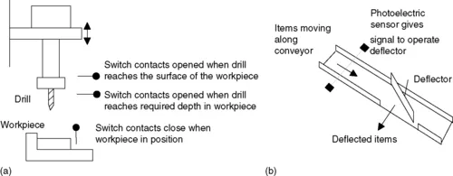
What type of task might a control system handle? It might be required to control a sequence of events, maintain some variable constant, or follow some prescribed change. For example, the control system for an automatic drilling machine (Figure 1.1a) might be required to start lowering the drill when the workpiece is in position, start drilling when the drill reaches the workpiece, stop drilling when the drill has produced the required depth of hole, retract the drill, and then switch off and wait for the next workpiece to be put in position before repeating the operation. Another control system (Figure 1.1b) might be used to control the number of items moving along a conveyor belt and direct them into a packing case. The inputs to such control systems might come from switches being closed or opened; for example, the presence of the workpiece might be indicated by it moving against a switch and closing it, or other sensors such as those used for temperature or flow rates. The controller might be required to run a motor to move an object to some position or to turn a valve, or perhaps a heater, on or off.
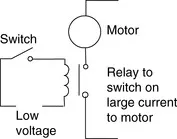
What form might a controller have? For the automatic drilling machine, we could wire up electrical circuits in which the closing or opening of switches would result in motors being switched on or valves being actuated. Thus we might have the closing of a switch activating a relay, which, in turn, switches on the current to a motor and causes the drill to rotate (Figure 1.2). Another switch might be used to activate a relay and switch on the current to a pneumatic or hydraulic valve, which results in pressure being switched to drive a piston in a cylinder and so results in the workpiece being pushed into the required position. Such electrical circuits would have to be specific to the automatic drilling machine. For controlling the number of items packed into a packing case, we could likewise wire up electrical circuits involving sensors and motors. However, the controller circuits we devised for these two situations would be different. In the “traditional” form of control system, the rules governing the control system and when actions are initiated are determined by the wiring. When the rules used for the control actions are changed, the wiring has to be changed.
1.1.1. Microprocessor-Controlled Systems
Instead of hardwiring each control circuit for each control situation, we can use the same basic system for all situations if we use a microprocessor-based system and write a program to instruct the microprocessor how to react to each input signal from, say, switches and give the required outputs to, say, motors and valves. Thus we might have a program of the form:
By changing the instructions in the program, we can use the same microprocessor system to control a wide variety of situations.
As an illustration, the modern domestic washing machine uses a microprocessor system. Inputs to it arise from the dials used to select the required wash cycle, a switch to determine that the machine door is closed, a temperature sensor to determine the temperature of the water, and a switch to detect the level of the water. On the basis of these inputs the microprocessor is programmed to give outputs that switch on the drum motor and control its speed, open or close cold and hot water valves, switch on the drain pump, control the water heater, and control the door lock so that the machine cannot be opened until the washing cycle is completed.
1.1.2. The Programmable Logic Controller
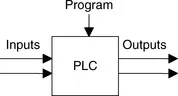
A programmable logic controller (PLC) is a special form of microprocessor-based controller that uses a programmable memory to store instructions and to implement functions such as logic, sequencing, timing, counting, and arithmetic in order to control machines and processes (Figure 1.3) and is designed to be operated by engineers with perhaps a limited knowledge of computers and computing languages. They are not designed so that only computer programmers can set up or change the programs. Thus, the designers of the PLC have preprogrammed it so that the control program can be entered using a simple, rather intuitive form of language (see Chapter 4). The term logic is used because programming is primarily concerned with implementing logic and switching operations; for example, if A or B occurs, switch on C; if A and B occurs, switch on D. Input devices (that is, sensors such as switches) and output devices in the system being controlled (motors, valves, etc.) are connected to the PLC. The operator then enters a sequence of instructions, a program, into the memory of the PLC. The controller then monitors the inputs and outputs according to this program and carries out the control rules for which it has been programmed.
PLCs have the great advantage that the same basic controller can be used with a wide range of control systems. To modify a control system and the rules that are to be used, all that is necessary is for an operator to key in a different set of instructions. There is no need to rewire. The result is a flexible, cost-effective system that can be used with control systems, which vary quite ...