
eBook - ePub
Marine Systems Identification, Modeling and Control
Tony Roskilly,Rikard Mikalsen
This is a test
Share book
- 190 pages
- English
- ePUB (mobile friendly)
- Available on iOS & Android
eBook - ePub
Marine Systems Identification, Modeling and Control
Tony Roskilly,Rikard Mikalsen
Book details
Book preview
Table of contents
Citations
About This Book
Marine Systems Identification, Modeling and Control is a concise, stand-alone resource covering the theory and practice of dynamic systems and control for marine engineering students and professionals. Developed from a distance learning CPD course on marine control taught by the authors, the book presents the essentials of the subject, including system representation and transfer, feedback control and closed loop stability. Simulation code and worked examples are provided for both Scilab and MATLAB, making it suitable for both those without access to expensive software and those using MATLAB in a professional setting. This title considers the key topics without superfluous detail and is illustrated with marine industry examples.
- Concise and practical, covering the relevant theory without excessive detail
- Industry-specific examples and applications for marine engineering students and professionals
- Clearly presents key topics of the subject, including system representation and transfer, feedback control and closed loop stability, making it ideal for self-study or reference
- Simulation code and worked examples using Scilab and MATLAB provided on the book's companion website
Frequently asked questions
How do I cancel my subscription?
Can/how do I download books?
At the moment all of our mobile-responsive ePub books are available to download via the app. Most of our PDFs are also available to download and we're working on making the final remaining ones downloadable now. Learn more here.
What is the difference between the pricing plans?
Both plans give you full access to the library and all of Perlego’s features. The only differences are the price and subscription period: With the annual plan you’ll save around 30% compared to 12 months on the monthly plan.
What is Perlego?
We are an online textbook subscription service, where you can get access to an entire online library for less than the price of a single book per month. With over 1 million books across 1000+ topics, we’ve got you covered! Learn more here.
Do you support text-to-speech?
Look out for the read-aloud symbol on your next book to see if you can listen to it. The read-aloud tool reads text aloud for you, highlighting the text as it is being read. You can pause it, speed it up and slow it down. Learn more here.
Is Marine Systems Identification, Modeling and Control an online PDF/ePUB?
Yes, you can access Marine Systems Identification, Modeling and Control by Tony Roskilly,Rikard Mikalsen in PDF and/or ePUB format, as well as other popular books in Technology & Engineering & Military Science & Technology. We have over one million books available in our catalogue for you to explore.
Information
Chapter One
Introduction
Abstract
This chapter presents an introduction to automatic control systems, including a brief review of the history of control engineering, the structure of control systems, including open- and closed-loop systems, and system dynamics. Examples of control systems are provided, and the chapter also briefly reviews some advanced control engineering topics, as well as introducing leading software tools for control systems analysis.
Keywords
Control system
Open loop
Closed loop
Structure
Block diagram
System dynamics
Plant dynamics
Chapter Points
• Introduction to control systems.
• History and background.
• Open- and closed-loop systems.
• System dynamics.
• Software tools.
1.1 Introduction to Control Systems
Control engineering is the science of altering the behavior of a dynamic process in a beneficial way. By dynamic process, we mean a process whose output(s) change as a continuous, time-varying function of the input(s). A simple example is the temperature of a room controlled by a boiler and radiator. The input to the system is the desired room temperature and the manner in which the actual room temperature responds is a dynamic function dependent on the physical parameters associated with the boiler, room, and the external conditions.
Control systems are key components in a range of industrial areas and applications, including marine and mechanical engineering, industrial manufacturing, chemical and process engineering, aviation, space flight, and electrical systems. Control systems also surround us in everyday life, in applications such as thermostats (in, e.g., hot water tanks and refrigerators), washing machines, consumer electronics, traffic lights, car cruise controls, etc.
The use of a control system in a mechanism, device, or process may have many different objectives. Of highest importance is to ensure system stability, for example controlling the reaction rate in a chemical process to prevent it going out of control. Control systems may also be used to optimize the operation of a plant, such as the adjusting of fuel and air flow rates to an engine to maximize fuel efficiency and minimize emissions. The use of active roll stabilization in ships modifies the dynamic behavior of the vessel in order to improve passenger comfort. Control systems may also be used to improve inherent performance limitations of a system, for example, to speed up the dynamic response. An example of the latter is the control of modern fighter jets, where advanced control is used to stabilize the aircraft and provide improved high-speed manoeuvrability.
In addition to a controller, control systems also usually include other elements:
• Sensors are used to measure some physical property of the process or plant and thus provide information for the controller, e.g., a thermo-couple device to provide temperature data or an optical encoder to measure the rotation of a motor.
• Actuators transduce signals from the controller to provide the input to and cause a change in behavior of the process or plant, e.g., a hydraulic ram to rotate the rudder in a steering gear system, a heater, or an electric motor transmission to drive a link of a robotic arm.
It is important to keep in mind that these components may also influence the behavior of the overall control system, for example, if they have a slow response or provide inaccurate or noisy data.
1.2 History of Control Engineering
The field of control engineering has developed alongside the industrial revolution. The steam engine centrifugal governor, used by among others James Watt and illustrated in Figure 1.1, is often considered to be one of the first automatic controllers. The governor adjusts the steam supply to the engine according to the engine speed, ensuring stable operation under varying load conditions. (If the speed drops due to a load increase, the steam supply is increased, and vice versa.) These early control systems were developed by engineers in the mid-nineteenth century and were followed by a more formal mathematical analysis of dynamic systems by scientists such as James C. Maxwell and Oliver Heaviside.
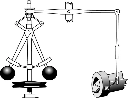
Figure 1.1 Centrifugal engine governor.
What is currently considered to be standard techniques in feedback control systems design, including proportional-integral-derivative (PID) feedback control, root locus, and frequency response methods, were developed around 1920-1950 by engineers and scientists such as Walter R. Evans, Hendrik W. Bode, and Harry Nyquist. Evans developed the root locus method, a graphical method to determine the behavior of a system for variations in some design parameter, such as controller gain. Bode and Nyquist developed techniques to study the time-domain stability and behavior of a system based on its frequency-domain characteristics. We will use these tools later.
1.3 Control System Structure
Control systems can, in general, be classified as either open loop or closed loop. Let us look at what these terms mean, and what the structure of a control system looks like.
1.3.1 Open-loop systems
In open-loop systems, the output of a plant or process may be controlled by varying the input, but the actual output has no influence upon that input. This can be illustrated with a simple block diagram as shown in Figure 1.2.
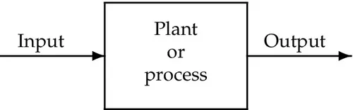
Figure 1.2 Open-loop control system.
An example of an open-loop control system is a room with a simple electric fire, illustrated in Figure 1.3. In this case, given an input (the mains supply switched on), the output (the room temperature) will eventually arrive at some constant level, i.e., the room temperature will become constant with time. The value of the output is dependent on the prevailing conditions or plant behavior, in this case the size of the heater and the heat losses from the room. If the rate of heat loss changes, for example, due to a change in outside temperature (external disturbance) or if someone opens a window (change in the plant), the room temperature will eventually settle at a new and different steady-state value. The open-loop control system does not know about the change in temperature and is there...