Written by the leading experts in computational materials science, this handy reference concisely reviews the most important aspects of plasticity modeling: constitutive laws, phase transformations, texture methods, continuum approaches and damage mechanisms. As a result, it provides the knowledge needed to avoid failures in critical systems udner mechanical load.
With its various application examples to micro- and macrostructure mechanics, this is an invaluable resource for mechanical engineers as well as for researchers wanting to improve on this method and extend its outreach.
eBook - ePub
Crystal Plasticity Finite Element Methods
in Materials Science and Engineering
- English
- ePUB (mobile friendly)
- Available on iOS & Android
eBook - ePub
Crystal Plasticity Finite Element Methods
in Materials Science and Engineering
About this book
Trusted by 375,005 students
Access to over 1.5 million titles for a fair monthly price.
Study more efficiently using our study tools.
Information
1
Introduction to Crystalline Anisotropy and the Crystal Plasticity Finite Element Method
Crystalline matter is mechanically anisotropic. This means that the instantaneous and time-dependent deformation of crystalline aggregates depends on the direction of the mechanical loads and geometrical constraints imposed. This phenomenon is due to the anisotropy of the elastic tensor, Figure 1.1, and to the orientation dependence of the activation of the crystallographic deformation mechanisms (dislocations, twins, martensitic transformations), Figure 1.2.
Figure 1.1 Elastic anisotropy in a polycrystal resulting from superposition of single-crystal anisotropy.
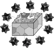
Figure 1.2 Plastic anisotropy in a single crystal due to distinct crystallography.
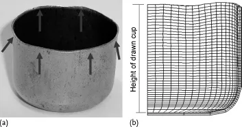
An essential consequence of this crystalline anisotropy is that the associated mechanical phenomena such as material strength, shape change, ductility, strain hardening, deformation-induced surface roughening, damage, wear, and abrasion are also orientation-dependent. This is not a trivial statement as it implies that mechanical parameters of crystalline matter are generally tensor-valued quantities. Another major consequence of the single-crystal elastic-plastic anisotropy is that it adds up to produce also macroscopically directional properties when the orientation distribution (crystallographic texture) of the grains in a polycrystal is not random. Figure 1.3a,b shows such an example of a plain carbon steel sheet with a preferred crystal orientation (here high probability for a crystallographic {111} plane being parallel to the sheet surface) after cup drawing. Plastic anisotropy leads to the formation of an uneven rim (referred to as ears or earing) and a heterogeneous distribution of material thinning during forming. It must be emphasized in that context that a random texture is not the rule but a rare exception in real materials. In other words, practically all crystalline materials reveal macroscopic anisotropy.
Figure 1.3 Consequence of plastic anisotropy when drawing a textured sheet into a cup. The orientation distribution before deformation exhibits a high volume fraction of grains with a crystallographic [111] axis parallel to the sheet normal. The arrows in (a) mark six ears resulting from preferential material flow. (b) The corresponding crystal plasticity finite element simulation.
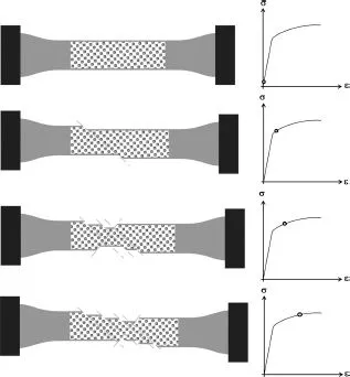
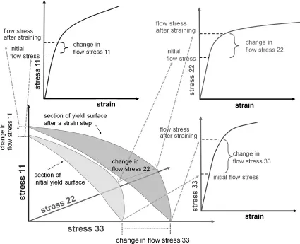
A typical example of such macroscopic anisotropy is the uniaxial stress-strain curve, which is the most important mechanical measure in the design of structural materials. The introductory statement made above implies that uniaxial stressstrain curves represent an incomplete description of plastic deformation as they reduce a six-dimensional yield surface and its change upon loading to a one-dimensional (scalar) yield curve, see Figure 1.4. Another consequence of this statement is that the crystallographic texture (orientation distribution) and its evolution during forming processes is a quantity that is inherently connected with plasticity theory, more precisely, with the anisotropy of the underlying plasticity mechanisms. Texture can, hence, be used to describe the integral anisotropy of polycrystals in terms of the individual tensorial behavior of each grain and the orientation-dependent boundary conditions among the crystals. Formally, the connection between shear and texture evolution becomes clear from the fact that any deformation gradient can be expressed as the combination of its skew-symmetric portion, which represents a pure rotation leading to texture changes if not matched by the rotation implied by plastic shear, and a symmetric tensor that is a measure of pure stretching. Plastic shear, hence, creates both shape and orientation changes, except for certain highly symmetric shears. Therefore, a theory of the mechanical properties of crystals must include, first, the crystallographic and anisotropic nature of those mechanisms that create shear and, second, the orientation(s) of the crystal(s) studied relative to the boundary conditions applied (e.g., loading axis, rolling plane).
Figure 1.4 Flow stress and strain hardening of anisotropic materials are tensor quantities.
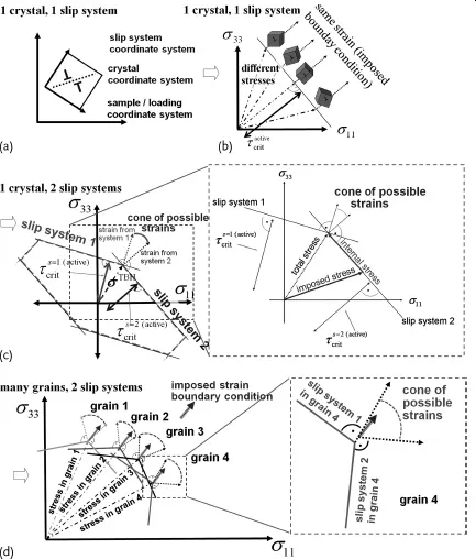
Early approaches to describe anisotropic plasticity under simple boundary conditions considered these aspects, such as the Sachs (1928), Taylor (1938), Bishop-Hill, and Kröner (1961) formulations. However, these approaches were neither designed for considering explicitly the mechanical interactions among the crystals in a polycrystal nor for responding to complex internal or external boundary conditions, see Figure 1.5a-d. Instead, they are built on certain simplifying assumptions of strain or stress homogeneity to cope with the intricate interactions within a polycrystal.
Figure 1.5 The increasing complexity of crystalscale micromechanics with respect to the equilibrium of the forces and the compatibility of the displacements for different situations: (a, b) Single-slip situation in a single crystal presented in stress space. (c) Portion of a single-crystal yield surface with three slip systems. (d) Multislip situation in a polycrystal where all different crystals have to satisfy an assumed imposed strain in their respective yield corners. If the strain is homogeneous, this situation leads to different stresses in each crystal (Raabe et al., 2002a, 2004a). τcrit: critical shear stress; σTBH: Taylor–Bishop–Hill stress state (stress required to reach a yield corner).
For that reason variational methods in the form of finite element approximations have gained enormous momentum in the field of crystal mechanical modeling. These methods, which are referred to as crystal plasticity finite element (CPFE) models, are based on the variational solution of the equilibrium of the forces and the compatibility of the displacements using a weak form of the principle of virtual work in a given finite-volume element. The entire sample volume under consideration is discretized into such elements. The essential step which renders the deformation kinematics of this approach a crystal plasticity formulation is the fact that the velocity gradient is written in dyadic form. This reflects the tensorial crystallographic nature of the underlying defects that lead to shear and, consequently, to both shape changes (symmetric part) and lattice rotations (skew-symmetric part), see Chapter 3. This means that the CPFE method has evolved as an attempt to employ some of the extensive knowledge gained from experimental and theoretical studies of single-crystal deformation and dislocations to inform the further development of continuum field theories of deformation. The general framework supplied by variational crystal plasticity formulations provides an attractive vehicle for developing a comprehensive theory of plasticity that incorporates existing knowledge of the physics of deformation processes (Arsenlis et al., 2004; Curtin and Miller, 2003; Vitek, Mrovec, and Bassani, 2004a) into the computational tools of continuum mechanics (Zienkiewicz, 1967; Zienkiewicz and Taylor, 2005) with the aim to develop advanced and physically based design methods for engineering applications (Zhao et al., 2004a).
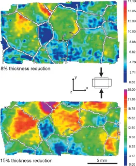
One main advantage of CPFE models lies in their capability to solve crystal mechanical problems under complicated internal and/or external boundary conditions. This aspect is not a mere computational advantage, but it is an inherent part of the physics of crystal mechanics since it enables one to tackle those boundary conditions that are imposed by inter- and intragrain micro-mechanical interactions, Figure 1.6 (Sachtleber, Zhao, and Raabe, 2002). This is not only essential to study in-grain or grain cluster mechanical problems but also to better understand the often quite abrupt mechanical transitions at interfaces (Raabe et al., 2003).
Figure 1.6 Experimental example of the heterogeneity of plastic deformation at the grain and subgrain scale using an aluminum oligocrystal with large columnar grains (Sachtleber, Zhao, and Raabe, 2002). The images show the distribution of the accumulated von Mises equivalent strain in a specimen after Δγ/γ0 = 8 and 15% thickness reduction in plane strain (γ0 is the initial sample height). The experiment was conducted in a lubricated channel-die setup. White lines indicate high-angle grain boundaries derived from electron backscatter diffraction microtexture measurements. The equivalent strains (determined using digital image correlation) differ across some of the grain boundaries by a factor of 4–5, giving evidence of the enormous orientation-dependent heterogeneity of plasticity even in pure metals.
However, the success of CPFE methods is not only built on their efficiency in dealing with complicated boundary conditions. They also offer high flexibility with respect to including various constitutive formulations for plastic flow and hardening at the elementary shear system level. The constitutive flow laws that were suggested during the last few decades have gradually developed from empirical viscoplastic formulations (Asaro and Rice, 1977; Rice, 1971) into microstructurebased multiscale models of plasticity including a variety of size-dependent effects and interface mechanisms (Arsenlis and Parks, 1999, 2002; Arsenlis et al., 2004; Cheong and Busso, 2004; Evers, Brekelmans, and Geers, 2004a,b; Evers et al., 2002; Ma and Roters, 2004; Ma, Roters, and Raabe, 2006a,b). In this context it should be emphasized that the finite element method itself is not the actual model but the variational solver for the underlying constitutive equations. Since its first introduction by Peirce et al. (1982), the CPFE method has matured into a whole family of constitutive and numerical formulationswhich have been applied to a broad variet...
Table of contents
- Cover
- Title
- Copyright
- Notation
- Preface
- 1: Introduction to Crystalline Anisotropy and the Crystal Plasticity Finite Element Method
- Part One: Fundamentals
- Part Two: The Crystal Plasticity Finite Element Method
- Part Three: Application
- References
- Index
Frequently asked questions
Yes, you can cancel anytime from the Subscription tab in your account settings on the Perlego website. Your subscription will stay active until the end of your current billing period. Learn how to cancel your subscription
No, books cannot be downloaded as external files, such as PDFs, for use outside of Perlego. However, you can download books within the Perlego app for offline reading on mobile or tablet. Learn how to download books offline
Perlego offers two plans: Essential and Complete
- Essential is ideal for learners and professionals who enjoy exploring a wide range of subjects. Access the Essential Library with 800,000+ trusted titles and best-sellers across business, personal growth, and the humanities. Includes unlimited reading time and Standard Read Aloud voice.
- Complete: Perfect for advanced learners and researchers needing full, unrestricted access. Unlock 1.5M+ books across hundreds of subjects, including academic and specialized titles. The Complete Plan also includes advanced features like Premium Read Aloud and Research Assistant.
We are an online textbook subscription service, where you can get access to an entire online library for less than the price of a single book per month. With over 1.5 million books across 990+ topics, we’ve got you covered! Learn about our mission
Look out for the read-aloud symbol on your next book to see if you can listen to it. The read-aloud tool reads text aloud for you, highlighting the text as it is being read. You can pause it, speed it up and slow it down. Learn more about Read Aloud
Yes! You can use the Perlego app on both iOS and Android devices to read anytime, anywhere — even offline. Perfect for commutes or when you’re on the go.
Please note we cannot support devices running on iOS 13 and Android 7 or earlier. Learn more about using the app
Please note we cannot support devices running on iOS 13 and Android 7 or earlier. Learn more about using the app
Yes, you can access Crystal Plasticity Finite Element Methods by Franz Roters,Philip Eisenlohr,Thomas R. Bieler,Dierk Raabe in PDF and/or ePUB format, as well as other popular books in Technology & Engineering & Materials Science. We have over 1.5 million books available in our catalogue for you to explore.