- 232 pages
- English
- ePUB (mobile friendly)
- Available on iOS & Android
eBook - ePub
Electronic Components and Technology
About this book
Most introductory textbooks in electronics focus on the theory while leaving the practical aspects to be covered in laboratory courses. However, the sooner such matters are introduced, the better able students will be to include such important concerns as parasitic effects and reliability at the very earliest stages of design. This philosophy has kept Electronic Components and Technology thriving for two decades, and this completely updated third edition continues the approach with a more international outlook.
Not only does this textbook introduce the properties, behavior, fabrication, and use of electronic components, it also helps students grasp and apply sound engineering practice by incorporating in-depth discussions on topics such as safety and reliability. The author employs a holistic treatment that clearly demonstrates how electronic components and subsystems work together, reinforcing the concepts with numerous examples, case studies, problems, illustrations, and objectives. This edition was updated to reflect advances and changes to industrial practice, including packaging technologies, digital oscilloscopes, lead-free solders, and new battery technologies. Additionally, the text's scope now extends to include terminology and standards used worldwide.
Including coverage of topics often ignored in other textbooks on the subject, Electronic Components and Technology, Third Edition encourages students to be better, more thoughtful designers and prepares them with current industrial practices.
Trusted by 375,005 students
Access to over 1.5 million titles for a fair monthly price.
Study more efficiently using our study tools.
Information
Introduction |
1 |
Modern electronic engineering products are found in a wide range of applications environments from the floor of the deep ocean (submarine cable repeaters) to geostationary orbit (microwave transceivers on board communications satellites), from the factory floor (industrial process controllers and numerically controlled machine tools) to the office (computers and printers). They can be found in the home (audio and video systems and microwave ovens), in schools (computers and pocket calculators), in hospitals (computerized tomography [CT] and magnetic resonance imaging [MRI] scanners, bedside monitors), inside the human body (heart pacemakers), and inside road vehicles (electronic ignition and engine management, antilock braking). Electronic products can also be found in the pocket (portable phones, personal audio, and video players). These products may be mass produced by the million, or they may be one-off special systems. They may be intended to last for decades, or they may be designed deliberately for a fairly short life. They should all be fit for their intended purpose and be of significant use to their users.
All electronic products depend on the physical and electrical properties of insulating, conducting, and especially semiconducting materials, but by and large, the designer of an electronic product works with components and technologies, such as integrated circuit (IC) technology, rather than with basic materials. A critical aspect of product design is the interconnection of components, and for this reason this book starts with a chapter covering the technology of interconnection. The technology of interconnecting electronic components, circuits, and subsystems was, until the publication of this book, often neglected in electronic engineering texts at degree level. It is true that the detailed layout of a printed circuit board (PCB) is not a task likely to be undertaken by a graduate engineer unless the PCB is to carry high-frequency or high-speed circuitry. Nevertheless, a PCB has electrical properties and its design, together with the choice of components to go on it, can have a significant effect on the performance, the cost of production, the production yield, and the reliability and maintainability of the assembled board, and quite likely the product of which it is a part. Jointing techniques, especially soldering, are of tremendous importance in electronic engineering, and solder is an engineering material that should be specified as carefully as a mechanical engineer specifies structural steel: what type of solder is best suited to a particular application? In many cases, just “solder” will not do.
The third chapter deals with IC technology. Only a few engineers are involved in high-volume IC design, but a more significant number design or use semicustom ICs. Consequently, the treatment in this book is not for the IC specialist: it is aimed at the much larger group of electronics engineers who will be using ICs or designing a gate-array or standard-cell IC of their own.
Competent electronics engineers need a good understanding of the components and subsystems from which their designs will be constructed and the instruments needed to test and characterize prototypes. They must be aware of not only the ideal behaviour of components, subsystems, and instruments, but also their performance limitations. The next three chapters, therefore, cover power sources and power supplies (an important class of electronic subsystem), passive electronic components, and instruments and measurement. To understand the performance limitations of components, an engineer must appreciate how the components are fabricated. To understand the performance limitations of power supplies and instruments, an engineer must appreciate the principles on which they operate. Chapters 5 and 6 cover these topics as well as provide factual information for reference.
The study of electronic components introduces the third major theme of this book: the parasitic effect. Real electronic components and circuits, as opposed to ideal ones, possess parasitic properties that are incidental to their intended properties. A wire-wound resistor, for example, is also inductive and has an impedance that varies with frequency. Heat is produced in significant quantity in some electronic systems, and positive design measures often have to be taken to remove it. Electromagnetic energy can radiate from electronic circuits and couple into other circuits, causing faulty operation. A chapter has been devoted to this and other parasitic electromagnetic effects. This book does not attempt to cover all possible parasitic effects: to do so would be impossible even in a much larger book and would serve little useful purpose. Electronics engineers must learn to expect parasitic effects and try to take them into account when designing electronic products.
So far this introduction has dealt with matters that affect design and performance in ways that are important at the beginning of the life of a product. Without an understanding of components, technology, and parasitic effects, the design engineer will not be able to design good products that meet the required level of performance at the required cost. Many electronic products, however, will have a life that lasts far longer than the designer’s interest in the design. It is during the operating life of a product that long-term effects become important. Components and materials age: they deteriorate physically and chemically, and ultimately they fail. The study of these problems and of the prediction of product life is known as reliability. Not surprisingly, the reliability of a product can be influenced by its design, for better or for worse, and if a product is capable of being repaired, the ease and expense with which it can be restored to working order can also be affected by decisions taken at the design stage. Reliability can also be influenced by a product’s operating environment. Did the designers consider the effects of temperature, humidity, corrosion, and dust? Is there some unknown environmental factor that will doom their product to early failure? As with parasitic effects, after introducing some of the many environmental hazards to electronic equipment, this book leaves the readers to consider what the problems of their products’ environment might be.
Lastly, this introduction has dealt with the electronic product itself: will it work and continue to work for long enough? Will it succumb to environmental stress? Engineers must also look at their designs from another viewpoint: will they do anyone, or the environment, any harm? All design engineers, including those working in electronic engineering, have a professional duty to consider safety when designing products, and in many countries a statutory (that is, legal) duty also. The final chapter introduces the subject of safety in electronic engineering.
Interconnection technology | 2 |
Objectives

All except the smallest of electronic systems are built up from subsystems or subassemblies that are in turn built from electronic components such as resistors, capacitors, transistors, integrated circuits (ICs), displays, and switches. A desktop personal computer, for example, is likely to be built from a power supply subsystem, a main circuit board, and a number of peripheral subsystems such as a CD/DVD drive and plugin memory modules. Small self-contained electronic products such as pocket calculators and portable phones are often built directly from components with no identifiable subsystems.
From the lowest level of component up to the system level, the constituent parts of an electronic system have to be interconnected electrically. The lowest level in the hierarchy of interconnection is the electrical joint. From the very earliest days of electronics, long before the invention of the transistor and integrated circuit, soldering has been an important technique for making electrical joints. Hand soldering is still used in prototype work, repair work, and, to a much lesser extent, production. Not all electrical joints in an electronic system need to be soldered: the technology of solderless wire-wrapping is well established in digital electronics, for both prototype and production wiring, and joints can also be made by insulation displacement, welding, or crimping. Components and subsystems are interconnected by wiring that can be in the form of either discrete wires and cables or printed circuits. A short case study at the end of this chapter illustrates the trend in electronic engineering over the last 20 years towards printed circuit interconnection wherever possible, avoiding discrete wiring because of the high cost of assembling and inspecting individual wires.
The printed circuit board, or PCB, is tremendously important in almost all applications areas of modern electronics. Not only does it provide a cheaply mass-produced means of interconnecting hundreds or thousands of individual components, but it also provides a mechanical mounting for the components.
In the very early days of electronics when thermionic (vacuum tube) valves were used, interconnection with discrete wiring was normal — but this was soon superceded with the advent of transistors by the introduction of printed circuit boards.
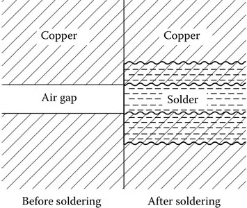
Figure 2.1 Diagrammatic representation of a soldered joint (not to scale).
Jointing
Several techniques are used in electronic engineering for making electrical joints. The most important of these is soldering, which is used mainly for attaching and jointing components to PCBs, but it is also widely used for jointing in cable connectors. Another important technology is solderless wire-wrapping, which finds application in prototype wiring for logic circuits and in production wiring of backplanes interconnecting PCBs. Welding is used in some specialized electronic applications and is a very important jointing technique in integrated circuit manufacture. Finally, in applications where soldering or welding cannot be used, mechanical crimping can make sound electrical joints.
Soldering
Solder is a low-melting-point alloy of tin and other metals, used for making electrical and mechanical joints between metals. Soldering does not melt the surfaces of the metals being joined, but adheres by dissolving into the solid surface. Figure 2.1 shows an idealized cross-section of a soldered joint illustrating this point. Soldered joints can be made by hand using an electrically heated soldering iron or by a mass-soldering process in which all the joints on a PCB are made in one automated operation. Both techniques are important, and they are described in detail below and in a later section of this chapter.
In the twentieth century, solders used in electronics were almost always alloys of tin and lead. From July 2006, the European Union (EU) has required lead (and many other toxic substances) to be eliminated from electronic and other products, and therefore lead-free solders are now used in place of tin–lead solders. Because of the historical importance of tin–lead solder in electronics, we start with its properties before progressing to the characteristics of lead-free solders.
Commercial tin–lead solders were available with several different proportions of tin to lead and with traces of other metals to enhance their properties. Tin and lead are soft metals with melting points of 232°C and 327°C respectively. Alloys of these metals generally start to melt at a temperature of 183°C, which is lower than the melting temperature of either pure metal. Figure 2.2 shows a simplified phase diagram for tin–lead alloys. The ratio (by weight) of tin to lead is plotted horizontally with 100% lead on the left and 100% tin on the right. The vertical scale represents temperature. In the top region of the diagram, above the line extending from the melting point of lead at 327°C across to the melting point of tin at 232°C via the point at a tin:lead ratio of 63:37 and a temperature of 183°C, the alloys are liquid. The bottom region of the diagram represents the ranges of temperature and tin:lead ratio over which the alloys are solid. The two triangular regions represent temperatures and compositions where the alloys are in a plastic state consisting partly of solid and partly of liquid. The alloy with a tin:lead ratio of 63:37 is the only one that changes sharply from solid to liquid at a single temperature. This alloy is known as a eutectic alloy. It is fully liquid at the lowest possible temperature for a tin–lead alloy.
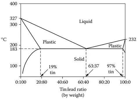
Figure 2.2 Phase diagram for tin–lead solder alloys (simplified).
Phase diagrams in general and the tin–lead phase diagram in particular are discussed by Anderson et al. (1990).
The proportion of tin (by weight) is conventionally stated first.
For general electronic jointing, a 60:40 solder was used, which is fully molten at about 188°C. 40:60 solder, which is fully molten at about 234°C, was a...
Table of contents
- Cover
- Half Title
- Title Page
- Copyright Page
- Table of Contents
- Preface to the Second Edition
- Preface
- Acknowledgments
- Author
- 1 Introduction
- 2 Interconnection technology
- 3 Integrated circuits
- 4 Power sources and power supplies
- 5 Passive electronic components
- 6 Instruments and measurement
- 7 Heat management
- 8 Parasitic electrical and electromagnetic effects
- 9 Reliability and maintainability
- 10 Environmental factors and testing
- 11 Safety
- References
- Answers to problems
- Index
Frequently asked questions
Yes, you can cancel anytime from the Subscription tab in your account settings on the Perlego website. Your subscription will stay active until the end of your current billing period. Learn how to cancel your subscription
No, books cannot be downloaded as external files, such as PDFs, for use outside of Perlego. However, you can download books within the Perlego app for offline reading on mobile or tablet. Learn how to download books offline
Perlego offers two plans: Essential and Complete
- Essential is ideal for learners and professionals who enjoy exploring a wide range of subjects. Access the Essential Library with 800,000+ trusted titles and best-sellers across business, personal growth, and the humanities. Includes unlimited reading time and Standard Read Aloud voice.
- Complete: Perfect for advanced learners and researchers needing full, unrestricted access. Unlock 1.5M+ books across hundreds of subjects, including academic and specialized titles. The Complete Plan also includes advanced features like Premium Read Aloud and Research Assistant.
We are an online textbook subscription service, where you can get access to an entire online library for less than the price of a single book per month. With over 1.5 million books across 990+ topics, we’ve got you covered! Learn about our mission
Look out for the read-aloud symbol on your next book to see if you can listen to it. The read-aloud tool reads text aloud for you, highlighting the text as it is being read. You can pause it, speed it up and slow it down. Learn more about Read Aloud
Yes! You can use the Perlego app on both iOS and Android devices to read anytime, anywhere — even offline. Perfect for commutes or when you’re on the go.
Please note we cannot support devices running on iOS 13 and Android 7 or earlier. Learn more about using the app
Please note we cannot support devices running on iOS 13 and Android 7 or earlier. Learn more about using the app
Yes, you can access Electronic Components and Technology by Stephen Sangwine in PDF and/or ePUB format, as well as other popular books in Technologie et ingénierie & Ingénierie de l'électricité et des télécommunications. We have over 1.5 million books available in our catalogue for you to explore.