![]()
Chapter 1
Getting Started with Autodesk® Inventor®
In this chapter, you will be introduced to the concept of parametric 3D design and the general tools and interface of Inventor. This chapter will focus on the concepts of parametric modeling and the workflow, tools, and interface elements found in the Autodesk® Inventor® software that are used to turn your ideas into a design.
In this chapter, you'll learn to:
- Create parametric designs
- Get the “feel” of Inventor
- Use the Inventor graphical interface
- Work with Inventor file types
- Understand how project search paths work
- Set up library and Content Center paths
- Create and configure a project file
- Determine the best project type for you
Understanding Parametric Design
Autodesk Inventor is first and foremost 3D parametric modeling software. And although it has capabilities reaching far beyond the task of creating 3D models, it is important for you to understand the fundamentals of parametric 3D design. The term parametric refers to the use of design parameters to construct and control the 3D model you create. For instance, you might begin a design by creating a base sketch to define the profile of a part. In this sketch you would use dimensions as parameters to control the length and width of the sketch. The dimensional parameters allow you to construct the sketch with precise inputs.
Creating a Base Sketch
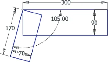
Well-constructed parts start with well-constructed sketches. Typically, the 3D model starts with a 2D sketch, which is assigned dimensions and 2D sketch constraints to control the general size and shape. These dimensions and constraining geometries are the parameters, or input points, that you would then change to update or edit the sketch. For instance, Figure 1.1 shows a base sketch of a part being designed.
You can see four dimensions placed on the two rectangles defining the length and width of each along with a fifth dimension controlling the angle at which the two rectangles relate. These dimensions are parameters, and if you were to change one of them at any point during the design or revision of the part, the sketch would update and adjust to the change.
An important part of working with sketches is the concept of a fully constrained sketch. Fully constrained simply means that all of the needed dimensions and sketch constraints have been applied to achieve a sketch that cannot be manipulated accidentally or as an unintentional consequence of an edit. For instance, if you were to sketch four lines to define a rectangle, you would expect two dimensions to be applied, defining the length and width. But you would also need to use 2D sketch constraints to constrain the lines so that they would stay perpendicular and equal to one another if one of the dimensions were to change. Without the sketch constraints, a dimensional edit to make the rectangle longer might result in a trapezoid or a parallelogram rather than the longer rectangle you anticipated. By fully constraining a sketch, you can anticipate the way in which it will update. Inventor helps you with this concept by automatically applying many sketch constraints, and by reporting when a sketch is fully constrained. This will be covered in more detail in Chapter 3, “Sketch Techniques.”
Creating a Base Feature
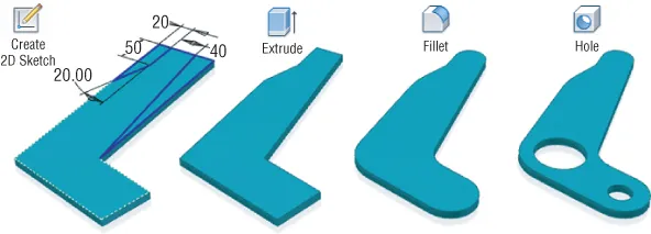
Not only do you add 2D sketch parameters; you also add parameters to control the 3D properties of parts. This is done by using the sketch to create a feature such as an extrusion to give a depth value to the sketch. The depth dimension is a parameter as well, and it can be updated at any time to adjust the part model as required. Figure 1.2 shows the sketch from Figure 1.1 after it has been given a depth using the Extrude tool.
Adding More Features
Once the part is three-dimensional, more sketches can be added to any of the faces of the 3D shape, and those new sketches can be used to create some feature that further defines the form and function of the design. The model is then enhanced with more features, such as holes, fillets, and chamfers, until it is complete. Each added feature is controlled by still more parameters defined by you, the designer. If a change is required, you simply update the parameter and the model updates accordingly. This type of parametric design allows you to build robust and intelligent models very quickly and update them even faster. Figure 1.3 illustrates the typical workflow of adding secondary features to a base feature to fully realize the part design, in this case a simple pivot link.
Using the Part in an Assembly
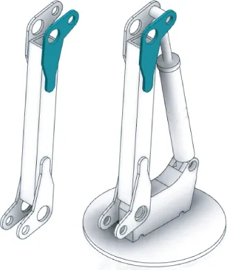
Just as well-constructed parts start with well-constructed sketches, well-constructed assemblies start with well-constructed parts. Once the part model is built up from the features you create, you can use it in an assembly of other parts created in the same manner. You can copy the part to create multiple instances of the same part, and you can copy the part file to create variations of the original part. To assemble parts, you create geometric relationships called assembly constraints defining how the parts go together. The constraints are parameters that can be defined and revised by you at any time in the design process as well. Part models can be arranged into small assemblies and placed into larger assemblies to create a fully realized subassembly structure that matches the way your design will be built on the shop floor. Figure 1.4 shows the part model from the previous illustrations placed multiple times in a subassembly, and then that subassembly placed in a top-level assembly.
Making Changes
Once parts are created, they are then used in assemblies, which also employ parameters to define the offsets and mating relationships between assembled parts. Designing with the use of parameters allows you to make edits quickly and lends itself to creating product configurations, where parameter values are changed to create variations of a basic design.
Of course, as with building anything, there are general rules and best practices to be learned and followed to prevent your work from “falling apart.” For instance, what if the pivot link used in the previous examples were to incur a design change that made one leg of the link longer? How would the holes be affected? Should they stay in the same place? Or should they stay at some defined distance from one end or the other?
Anticipating changes to the model is a large part of being successful with Inventor. Imagine, for instance, that a simple design change required that the pivot link become 50 millimeters longer on one leg. This should be a simple revision that requires you only to locate the dimension controlling that leg length and change the parameter value. Unfortunately, if you did not follow the best-practices guidelines when creating the part originally, the change in the length might displace the secondary features such as holes and material cuts and require you to stop and fix each of those as well. This is one of the most frustrating parts of learning Inventor for any new user who has not taken the time to learn or follow the known best practices of parametric modeling. Fortunately for you, within the pages of this book you will learn how to create models that are easy to update and do not “fall apart” during design changes.
Understanding History-Based Modeling and Dependencies
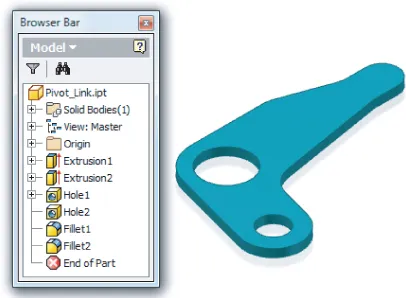
Inventor is often referred to as a history-based modeler, meaning that as you create sketches and turn them into features and then add more features and still more features, each addition is based on a previous feature, and so the model is said to have history. This history is recorded and tracked in the Model browser. The Model browser is a panel that displays on-screen and shows every feature you create during the design of your part. Figure 1.5 shows the Model browser for the pivot link file.
You can see that each feature is listed in the browser in the order in which it was created, forming a history tree. To create a part that handles changes predictably, you must create a solid foundation on which to build the rest of the model. In most cases, when you are designing a part model you will start with a sketch, much like the one shown back in Figure 1.1. This base ske...