![]()
1
Technical Considerations
Use of the Imaging Department
Good communication between clinicians and radiologists is vital because the radiology department needs to understand the clinical problem in order to carry out appropriate tests and to interpret the results in a meaningful way. Also, clinicians need to understand the strengths and limitations of the answers provided.
Sensible selection of imaging investigations is of great importance. There are two opposing philosophies. One approach is to request a battery of investigations, aimed in the direction of the patient’s symptoms, in the hope that something will turn up. The other approach is ‘trial and error’: decide one or two likely diagnoses and carry out the appropriate test to support or refute these possibilities. We favour the selective approach as there is little doubt that the answers are usually obtained less expensively and with less distress to the patient. This approach depends on critical clinical evaluation; the more experienced the doctor, the more accurate he or she becomes in choosing appropriate tests.
Laying down precise guidelines for requesting imaging examinations is difficult because patients are managed differently in different centres. Box 1.1 provides important points when requesting imaging investigations.
Box 1.1 Best Practice When Requesting Imaging Investigations
- Only request an examination if it is likely to affect patient management
- The time interval between follow-up examinations should be appropriate and depends on the natural history of disease
- Localize the clinical problem as specifically as possible prior to imaging in order to reduce over-investigation and excess radiation exposure
- Careful consideration should be given to which imaging procedure is likely to give the relevant diagnostic information most easily
- Any investigations that have been requested but become unnecessary should be cancelled
- Examinations that minimize or avoid ionizing radiation should be chosen when possible
- Good communication with the radiologists is key to ensuring appropriate investigation pathways
Conventional Radiography
X-rays are absorbed to a variable extent as they pass through the body. The visibility of both normal structures and disease depends on this differential absorption. With conventional radiography there are four basic densities – gas, fat, all other soft tissues and calcified structures. X-rays that pass through air are least absorbed and, therefore, cause the most blackening of the radiograph, whereas calcium absorbs the most and so the bones and other calcified structures appear virtually white. The soft tissues, with the exception of fat, e.g. the solid viscera, muscle, blood, a variety of fluids, bowel wall, etc., all have similar absorptive capacity and appear the same shade of grey on conventional radiographs. Fat absorbs slightly fewer x-rays and, therefore, appears a little blacker than the other soft tissues. Traditionally, images were produced using a silver-based photographic emulsion but now they are recorded digitally and viewed on computer screens in most centres.
Projections are usually described by the path of the x-ray beam. Thus, the term PA (posteroanterior) view designates that the beam passes from the back to the front, the standard projection for a routine chest film. An AP (anteroposterior) view is taken from the front. The term ‘frontal’ refers to either PA or AP projection. The image on an x-ray film is two-dimensional. All the structures along the path of the beam are projected on to the same portion of the film. Therefore, it is often necessary to take at least two views to gain information about the third dimension. These two views are usually at right angles to one another, e.g. the PA and lateral chest film. Sometimes two views at right angles are not appropriate and oblique views are substituted.
Portable x-ray machines can be used to take films of patients on the ward or in the operating theatre. Such machines have limitations on the exposures they can achieve. This usually means longer exposure times and poorer quality films. The positioning and radiation protection of patients in bed is often inferior to that which can be achieved within the x-ray department. Consequently, portable films should only be requested when the patient cannot be moved safely to the x-ray department.
Computed Tomography
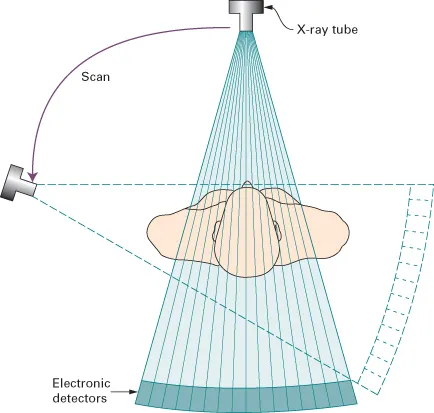
Computed tomography (CT) also relies on x-rays transmitted through the body. It differs from conventional radiography in that a more sensitive x-ray detection system is used, the images consist of sections (slices) through the body, and the data are manipulated by a computer. The x-ray tube and detectors rotate around the patient (Fig. 1.1). The outstanding feature of CT is that very small differences in x-ray absorption values can be visualized. Compared with conventional radiography, the range of densities recorded is increased approximately ten-fold. Not only can fat be distinguished from other soft tissues, but also gradations of density within soft tissues can be recognized, e.g. brain substance from cerebrospinal fluid, or tumour from surrounding normal tissues.
The patient lies with the body part to be examined within the gantry housing the x-ray tube and detectors. Although other planes are sometimes practicable, axial sections are by far the most frequent. The operator selects the level and thickness to be imaged: the usual thickness is between 1.25 and 2 mm (often viewed by aggregating adjacent sections so they become 5 mm thick). The patient is moved past an array of detectors within the machine. In effect, the data at multiple adjacent levels are collected continuously, during which time the x-ray beam traces a spiral path to create a ‘volume of data’ within the computer memory. Multidetector (multislice) CT acquires multiple slices (64, 128, 256 or 320 depending on the machine) during one rotation of the x-ray tube. Multidetector CT enables the examination to be performed in a few seconds, thereby enabling hundreds of thin sections to be obtained in one breath-hold. A relatively new development is dual source (or dual energy) CT. This technique allows a virtual non-contrast CT image to be derived from CT acquired with intravenous iodinated contrast medium (see later in chapter) allowing a reduction in radiation dose in certain CT protocols.
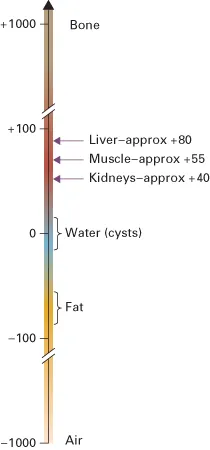
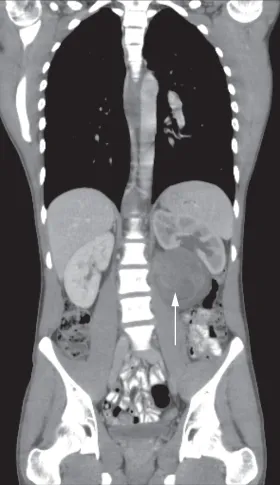
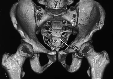
The data obtained from the multislice CT exposures are reconstructed into an image by computer manipulation. The computer calculates the attenuation (absorption) value of each picture element (pixel). Each pixel is 0.25–0.6 mm in diameter, depending on the resolution of the machine, with a height corresponding to the chosen section thickness. The resulting images are displayed on a monitor and can be stored electronically. The attenuation values are expressed on an arbitrary scale (Hounsfield units) with water density being zero, air density being minus 1000 units and bone density being plus 1000 units (Fig. 1.2). The range and level of densities to be displayed can be selected by controls on the computer. The range of densities visualized on a particular image is known as the window width and the mean level as the window level or window centre. CT is usually performed in the axial plane, but because attenuation values for every pixel are present in the computer memory it is possible to reconstruct excellent images in other planes, e.g. coronal (Fig. 1.3), sagittal or oblique, and even three-dimensional (3D) images (Fig. 1.4).
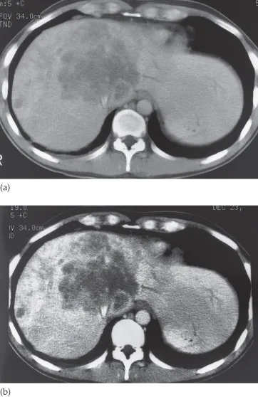
The human eye can only appreciate a limited number of shades of grey. With a wide window all the structures are visible, but fine details of density difference cannot be appreciated. With a narrow window width, variations of just a few Hounsfield units can be seen, but much of the image is either totally black or totally white and in these areas no useful information is provided. The effects of varying window width and level are illustrated in Figs 1.5 and 2.6.
Computed Tomography Angiography
Rapid intravenous injections of contrast media result in significant opacification of blood vessels, which, with multiplanar or 3D reconstructions, can be exploited to produce angiograms. CT angiography, along with magnetic resonance angiography, is gradually replacing conventional diagnostic angiography.
Artefacts
There are numerous CT artefacts. The...