![]()
1
Session 1: Structures, Materials and the Environment
The general question addressed here is how to ensure an efficient implementation of resources, to minimize environmental and biological impacts and to identify responsibilities. The resources concerned are aquaculture and fishing nets and oil-spill booms from the structural analysis point of view, but equally, software which through numerical modeling will also address the correct way to install structures.
1.1. FEM modeling of flexible structures made of cables, bars and nets
1.1.1. Introduction
This presentation concerns finite element method (FEM) modeling devoted to flexible structures, such as fishing gear and fish-farming cages.
The first part gives the basic hypothesis:
– the netting is discretized into triangular finite elements;
– the net twines remain straight in each triangular element;
– the water current is not affected by the structure;
– Young’s modulus is constant in twine traction and in twine compression.
The forces described in mathematical form are due to twine stiffness elongation The virtual work principle is used to relate the force (F) on the 3 vertexes of the triangular element with the position (X) of these vertexes. The equilibrium
is found using the Newton-Raphson method.
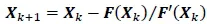
The position at iteration k+1 (Xk+1) is found using the position (Xk). The force (F(Xk)) and the derivative of force (F,(Xk)) at iteration k with the following equation:
Simulations have been carried out for trawls made of diamond and hexagonal meshes, for cod-ends with catch, and for floating fish cages. Comparisons are given when experimental data are available.
1.1.2. Details of study
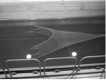
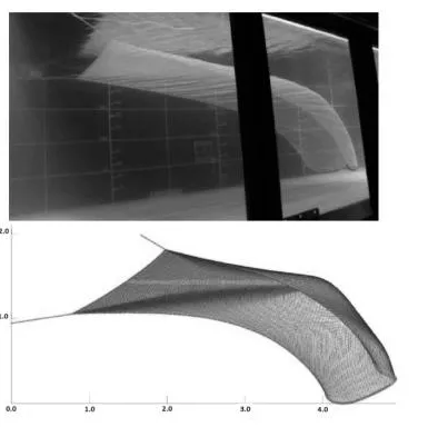
In a flume tank the netting looks like a surface as shown in Figure 1.1.
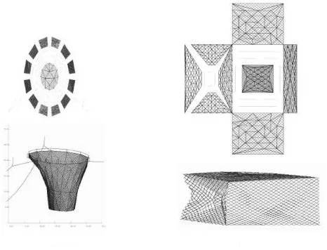
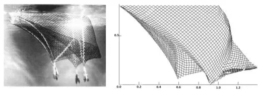
Two examples of netting structures are shown in Figure 1.2: a fish cage, on the left and a fish trap, on the right.
Figure 1.1. Netting surface
Figure 1.2. The two netting structures are modeled using triangular elements
In each triangular element, the twines have the same deformation.
This presentation focuses on the modeling of fishing gear and on the comparison of numerical and experimental results, carried out in hydrodynamic basins and flume tanks.
The netting drag modeling can be improved in the following way. The parameters are the water speed, the netting solidity and the angle. The possible formulations may be based on Morrison assumptions, Zhan studies [SUN 10], Pichot experimentations [PIC 09], Aarsnes tests [AAR 90] and those based on the pressure drop.
Figure 1.3 shows experimental and numerical results on a net surface dedicated to the improvement of netting drag modeling. The net surface boundary is connected to two tension ropes situated on the corners of its left-hand side, and is weighted on its right-hand side. A comparison between the surface geometries allows us to validate the model.
Figure 1.3. Comparison of net shape with free boundaries under hydrodynamic drag
A fishing cage is studied by both experimental and numerical modeling. The following figure shows the comparison between test and modeling. This cage is used for aquaculture in open seas.
Figure 1.4. Fishing cage
To go ahead with the triangular element defined by a set of cable (twine), it is proposed that we use a homogeneous triangular element having three degrees of freedom per node in translation Ui, Vi, Wi and equally three in rotation Θxi, Θyi, Θzi. We highlight the very low level of hydrodynamic drag force at the twine scale.
The discussion reveals the lack of available places in French marine waters for aquaculture plants.
1.2. Oil-boom models and full-scale tests
1.2.1. Introduction
Floating barriers named booms are moored during oil spill emergencies in the vicinity of a shore respecting geomorphology and environmental conditions to ensure containment or deviation of hydrocarbon slicks.
The Deepwater Horizon crisis in the Gulf of Mexico saw the largest deployment of containment booms, 4.2 million of feet or 1,280 km. One of the main problems encountered is the difficulty in handling the environmental conditions, the fabric structure performances and limitations, so that a positive response can be given to such a disaster.
The state of the art concerning oil booms focuses mainly on their hydrodynamic performances. Their behaviors are investigated under current and waves showing the Kelvin– Helmholtz instability of the oil–water interface. The relationship between boom design parameters and the mode of failure of oil containment is studied for a variety of wave and current combinations.
Our approach concerns the structural analysis of the flexible barrier under the external actions provided by the mooring system and the natural environment. To validate our mechanical studies, we describe a validation program based on full-scale experiments. Such ambitious programs have begun with test preparations at the sites of La Rochelle and Lorient (both in France), before the most promising experiment carried out in the Élorn estuary (also in France).
1.2.2. Details of study
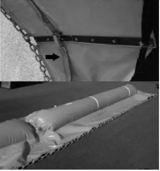
The junction between two boom elements shown in Figure 1.5 is built on a link between the chain, the leach (black arrow on the figure) and the coated fabric material. The FEM uses a mesh for each of these parts on the barrier.
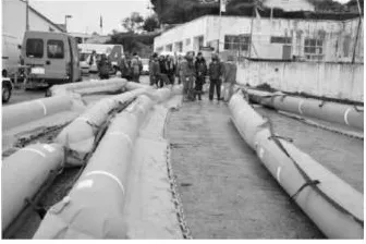
The emergency planning of the Élorn estuary begins by the inflation of the boom float before towing the barrier on the sea by ship. The following figure shows part of the 200-m-long barrier installed for the Élorn experiment of November 2009.
Figure 1.5. The junction between two boom elements
Figure 1.6. Inflated floating part and undersea skirt part of a boom
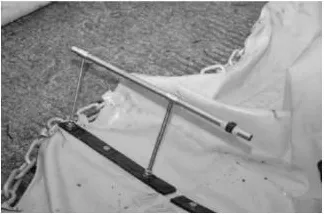
To measure the skirt angle under the sea-current action, a skirt angle stick support is fixed on a boom element junction. Figure 1.7 shows such a device where a 2-m-long stick is installed in the metallic tube.
Figure 1.7. Skirt angle stick support
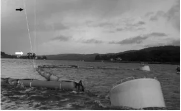
Figure 1.8 presents the skirt angle of the boom obtained by the direct measure given by the stick (white arrow in the figure) and the comparison with the threshold 10° value (black arrow in the figure). This threshold has been constructed by using numerical modeling of the oil–water flow around the boom.
Figure 1.8. The skirt angle is higher than the threshold efficiency value of 10°
The observation of the skirt angle suggests that an oil leakage by submersion may be observed if this boom configuration is used in the presence of drifting oil pollution.
From a mathematical point of view, our methodology is based on a 1st-order ordinary differential equation (ODE) giving us the curve of a hydrodynamic leach. This Cauchy problem allows an initial tension–angle solution of the threedimensional (3D) boom surface. The partial differential equation (PDE) of the 3D membrane is based on the elastic membrane equation with Dirichlet boundary condition at the level of float bottom in the vicinity of the sea surface. The FEM uses a four-node bilinear element and the Newton– Raphson method. The convergence of the solution of the nonlinear 3D problem is favored by using the ODE solution. Here we used embedded meshes going from one-dimensional (1D) to 3D domains.
As a result on boom stress we have observed a tension of 107 kg at the far coffer in Figure 1.8, while the 1st-order ODE equation will give 158 kg and the 3D mesh solution 207 kg. These three values indicate the magnitude order of the force applied on the right part of the boom. This force inclines the buoyancy coffer visible on the right in Figure 1.8. This coffer is represented by a circular mark on the upper right in Figure 1.9.
...