Part I
Getting Started with Circuit Analysis
Visit
www.dummies.com to learn more and do more with
For Dummies.In this part . . .
Discover what circuit analysis is all about.
Get the scoop on current and voltage behaviors in common circuit components and find out how to read circuit diagrams.
Familiarize yourself with Kirchhoff’s voltage law and Kirchhoff’s current law — two laws essential for creating connection equations.
Use source transformation and current and voltage divider techniques to simplify circuit analysis.
Chapter 1
Introducing Circuit Analysis
In This Chapter
Understanding current and voltage
Applying laws when you connect circuit devices
Analyzing circuits with algebra and calculus
Taking some mathematical shortcuts
Circuit analysis is like the psychoanalysis of the electrical engineering world because it’s all about studying the behavior of circuits. With any circuit, you have an input signal, such as a battery source or an audio signal. What you want to figure out is the circuit’s output — how the circuit responds to a given input.
A circuit’s output is either a voltage or a current. You have to analyze the voltages and currents traveling through each element or component in the circuit in order to determine the output, although many times you don’t have to find every voltage and every current within the circuit.
Circuit analysis is challenging because it integrates a variety of topics from your math and physics courses in addition to introducing techniques specific to determining circuit behavior. This chapter gives you an overview of circuit analysis and some of the key concepts you need to know before you can begin understanding circuits.
Getting Started with Current and Voltage
Being able to analyze circuits requires having a solid understanding of how voltage and current interact within a circuit. Chapter 2 gives you insight into how voltage and current behave in the types of devices normally found in circuits, such as resistors and batteries. That chapter also presents the basic features of circuit diagrams, or schematics.
The following sections introduce you to current and voltage as well as a direction-based convention that’s guaranteed to come in handy in circuit analysis.
Going with the flow with current
Current is a way of measuring the amount of electric charge passing through a given point within a certain amount of time. Current is a flow rate. The mathematical definition of a current is as follows:
The variable i stands for the current, q stands for the electrical charge, and t stands for time.
The charge of one electron is 1.609
× 10
–19 coulombs (C).
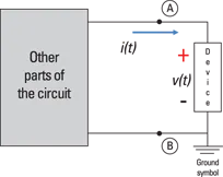
Current measures the flow of charges with dimensions of coulombs per second (C/s), or amperes (A). In engineering, the current direction describes the net flow of positive charges. Think of current as a through variable, because the flow of electrical charge passes through a point in the circuit. The arrow in Figure 1-1 shows the current direction.
Illustration by Wiley, Composition Services Graphics
Figure 1-1: Current direction, voltage polarities, and the passive sign convention.
Measuring current through a device requires just one point of measurement. As an analogy, say you’re asked to count the number of cars flowing through your long stretch of residential street for 10 minutes. You can count the number of cars from your home or your friend’s home next door or the house across the street. You need just one location point to measure the flow of cars.
Two types of current exist: alternating current (AC) and direct current (DC). With AC, the charges flow in both directions. With DC, the charges flow in just one direction.
If you have trouble keeping AC and DC straight, try this mnemonic device: AC means “always changing,” and DC means “doesn’t change.”
Recognizing potential differences with voltag...