The advance of variable speed drives systems (VSDs) engineering highlights the need of specific technical guidance provision by electrical machines and drives manufacturers, so that such applications can be properly designed to present advantages in terms of both energy efficiency and expenditure.
This book presents problems and solutions related to inverter-fed electrical motors. Practically orientated, the book describes the reasons, theory and analysis of those problems. Various solutions for individual problems are presented together with the complete design process, modelling and simulation examples with MATLAB/Simulink on the companion website.
A key focus of Variable Speed AC Drives with Inverter Output Filters is to examine the state variables estimation and motor control structures which have to be modified according to the used solution (filter). In most control systems the structure and parameters are taken into account to make it possible for precise control of the motor. This methodology is able to include modifications and extensions depending on specific control and estimation structures.
Highly accessible, this is an invaluable resource for practising R&D engineers in drive companies, power electronics & control engineers and manufacturers of electrical drives. Senior undergraduate and postgraduate students in electronics and control engineering will also find it of value.
Trusted by 375,005 students
Access to over 1 million titles for a fair monthly price.
The basic function of electric drives is to convert electrical energy to mechanical form (in motor mode operation) or from mechanical form to electrical energy (in generation mode). The electric drive is a multidisciplinary problem because of the complexity of the contained systems (Figure 1.1).
Figure 1.1 General structure of an electrical drive
It is important to convert the energy in a controllable way and with high efficiency and robustness. If we look at the structure of global consumption of electrical energy the significance is plain. In industrialized countries, approximately two thirds of total industrial power demand is consumed by electrical drives [1, 2].
The high performance and high efficiency of electric drives can be obtained only in the case of using controllable variable speed drives with sophisticated control algorithms [3, 4].
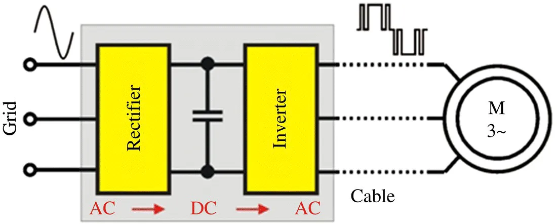
In the industry, the widely used adjustable speed electrical drives are systems with an induction motor and voltage inverter (Figure 1.2). Their popularity results mainly from good control properties, good robustness, high efficiency, simple construction, and low cost of the machines [5].
Figure 1.2 Electrical drive with voltage inverter and AC motor
Simple control algorithms for induction motors are based on the V/f principle. Because the reference frequency changes, the motor supply voltage has to be changed proportionally. In more sophisticated algorithms, systems such as field-oriented, direct torque, or multiscalar control have to be applied [6, 7] . Simultaneously, because of the estimation possibilities of selected controlled variables, for example, mechanical speed, it is possible to realize a sensorless control principle [7–10]. The sensorless speed drives are beneficial to maintain good robustness. Unfortunately, for sophisticated control methods, knowledge of motor parameters as well as high robustness of the drives against changes in motor parameters is required.
1.2 General Overview of AC Drives with Inverter Output Filters
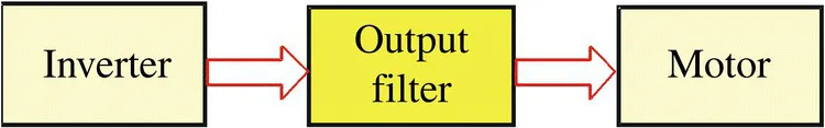
The inverter output voltage has a rectangular shape and is far from the sinusoidal one. Also, the use of semiconductor switches with short switching times causes high rates of rises of dV/dt voltages that initiate high levels of current and voltage disturbance [4, 11] . For this reason, it is necessary to apply filters between the inverter and the motor (Figure 1.3).
Figure 1.3 AC motor with voltage inverter and inverter output filter
The introduction of a filter at the inverter output disables the proper operation of advanced drive control systems because doing this introduces more passive elements (inductances, capacitances, and resistances), which are not considered in the control algorithm [4, 12, 13] . This irregularity is caused by amplitude changes and phase shifts between the first current component and the motor supply voltage, compared to the currents and voltages on the inverter output. This causes the appearance in the motor control algorithm of inaccurate measured values of current and voltage at the standard measuring points of the inverter circuit. A possible solution to this issue is the implementation of current and voltage sensors at the filter output. However, this solution is not applied in industry drive systems because the filter is an element connected to the output of the inverter. The implementation of external sensors brings an additional cable network and that increases the susceptibility of the system to disturbances, reduces the system reliability, and increases the total cost of the drive.
A better solution is to consider the structure and parameters of the filter in the control and estimation algorithms. This makes it possible to use the measurement sensors that are already installed in the classical voltage inverter systems.
The addition of the filter at the voltage inverter output is beneficial because of the limitation of disturbances at the inverter output by obtaining sinusoidal voltage and current waveforms. Noises and vibrations are reduced and motor efficiency is increased. Furthermore, output filters reduce overvoltages on the motor terminals, which are generated through wave reflections in long lines and can result in accelerated aging of insulation. Several filter solutions are also used for limiting motor leakage currents, ensuring a longer failure-free operation time of the motor bearings.
The application of an inverter output filter and its consideration in the control algorithm is especially beneficial for various drive systems such as cranes and elevators. In that application, a long connection between motor and inverter is common.
The limitation of disturbances in inverter output circuits is an important issue that is discussed in numerous publications [14–18]. To limit such current and voltage disturbances, passive or active filters are used [4, 15] . The main reasons for preferring passive filters are especially the economic aspects and the possibility of limiting current and voltage disturbances in drive systems with high dV/dt voltage.
The control methods presented so far in the literature (e.g., [8–10, 19–27]) for an advanced sensorless control squirrel cage motor are designed for drives with the motor directly connected to the inverter. Not using filters in many drives is the result of control problems because of the difference between the instantaneous current and voltage values at the filter output and the current and voltage values at the filter input. Knowledge of this values is needed in the drive system control [28, 29] . A sensorless speed control in a drive system with an induction motor is most often based on the knowledge of the first component of the current and voltage. The filter can be designed in such a way that it will not significantly influence the fundamental components and will only limit the higher harmonics. However, most output filter systems introduce a voltage drop and a current and voltage phase shift for the first harmonic [4, 30] . This problem is important especially for sinusoidal filters, which ensure sinusoidal output voltage and current waveforms.
Another problem that has received attention in the literature [16, 30–37] is the common mode current that occurs in drive systems with a voltage inverter. The common mode current flow reduces the motor durability because of the accelerated wear of bearings. This current might also have an effect on the wrong operation of other drives included in the same electrical grid and can cause rising installation costs, which could lead to the need for an increase in the diameter of earth wire. Such problems come from both the system topology and the applied pulse width modulation in the inverter, which are independent of the main control algorithms. Modifying the modulation method can cause a limitation of the common mode current [4, 30, 38].
This book presents the problems related to voltage-inverter-fed drive systems with a simultaneous output filter application. The authors have presented problems and searched for new solutions, which up to now, have not been presented in the literature. Therefore, this book introduces, among other topics, new state observer structures and control systems with LC filters.
The problem of drive systems with output filters, justifying the need for their application, is also explained. Moreover, the aim of this book is to present a way to control a squirrel cage induction motor and estimation of variables by considering the presence of the output filter, especially for drive systems without speed measurement.
Other discussed topics are several motor control structures that consider the motor filter as the control object. Such solutions are introduced for nonlinear-control drive systems and field-orientated control with load-angle control. Predictive current control with the presence of a motor choke is also analyzed. Solutions for systems with the estimation of state variables are presented, and the fault detection scheme for the mechanical part of the load torque transmission system is shown. Thus, for diagnostic purposes, state observer solutions were applied for drive systems with a motor filter.
The main points to be discussed are:
A motor filter is an essential element in modern inverter drive systems.
The introduction of a motor filter between the inverter and motor terminals changes the drive system structure in such a way that the drive system might operate incorrectly.
The correct control of the induction motor, especially for sensorless drives, requires consideration of the filter in the control and state variable estimation process.
Some of the presented problems in the book also refer to drive systems without filters. Those problems are predictive current c...
Table of contents
Cover
Title Page
Table of Contents
Foreword
Acknowledgments
About the Authors
Nomenclature
1 Introduction to Electric Drives with LC Filters
2 Problems with AC Drives and Voltage Source Inverter Supply Effects
3 Model of AC Induction Machine
4 Inverter Output Filters
5 Estimation of the State Variables in the Drive with LC Filter
6 Control of Induction Motor Drives with LC Filters
7 Current Control of the Induction Motor
8 Diagnostics of the Motor and Mechanical Side Faults
9 Multiphase Drive with Induction Motor and an LC Filter
10 General Summary, Remarks, and Conclusion
Appendix A: Synchronous Sampling of Inverter Output Current
Appendix B: Examples of LC Filter Design
Appendix C: Equations of Transformation
Appendix D: Data of the Motors Used in Simulations and Experiments
Appendix E: Adaptive Backstepping Observer
Appendix F: Significant Variables and Functions in Simulation Files
Index
End User License Agreement
Frequently asked questions
Yes, you can cancel anytime from the Subscription tab in your account settings on the Perlego website. Your subscription will stay active until the end of your current billing period. Learn how to cancel your subscription
No, books cannot be downloaded as external files, such as PDFs, for use outside of Perlego. However, you can download books within the Perlego app for offline reading on mobile or tablet. Learn how to download books offline
Perlego offers two plans: Essential and Complete
Essential is ideal for learners and professionals who enjoy exploring a wide range of subjects. Access the Essential Library with 800,000+ trusted titles and best-sellers across business, personal growth, and the humanities. Includes unlimited reading time and Standard Read Aloud voice.
Complete: Perfect for advanced learners and researchers needing full, unrestricted access. Unlock 1.4M+ books across hundreds of subjects, including academic and specialized titles. The Complete Plan also includes advanced features like Premium Read Aloud and Research Assistant.
Both plans are available with monthly, semester, or annual billing cycles.
We are an online textbook subscription service, where you can get access to an entire online library for less than the price of a single book per month. With over 1 million books across 990+ topics, we’ve got you covered! Learn about our mission
Look out for the read-aloud symbol on your next book to see if you can listen to it. The read-aloud tool reads text aloud for you, highlighting the text as it is being read. You can pause it, speed it up and slow it down. Learn more about Read Aloud
Yes! You can use the Perlego app on both iOS and Android devices to read anytime, anywhere — even offline. Perfect for commutes or when you’re on the go. Please note we cannot support devices running on iOS 13 and Android 7 or earlier. Learn more about using the app
Yes, you can access Variable Speed AC Drives with Inverter Output Filters by Jaroslaw Guzinski,Haitham Abu-Rub,Patryk Strankowski in PDF and/or ePUB format, as well as other popular books in Technology & Engineering & Power Resources. We have over one million books available in our catalogue for you to explore.