This classic manual on structural steelwork design was first published in 1955, since when it has sold many tens of thousands of copies worldwide. For the seventh edition of the Steel Designers' Manual all chapters have been comprehensively reviewed, revised to ensure they reflect current approaches and best practice, and brought in to compliance with EN 1993: Design of Steel Structures (the so-called Eurocode 3).
- English
- ePUB (mobile friendly)
- Available on iOS & Android
eBook - ePub
Steel Designers' Manual
About this book
In 2010 the then current European national standards for building and construction were replaced by the EN Eurocodes, a set of pan-European model building codes developed by the European Committee for Standardization. The Eurocodes are a series of 10 European Standards (EN 1990 – EN 1999) that provide a common approach for the design of buildings, other civil engineering works and construction products. The design standards embodied in these Eurocodes will be used for all European public works and are set to become the de-facto standard for the private sector in Europe, with probable adoption in many other countries.
Trusted by 375,005 students
Access to over 1.5 million titles for a fair monthly price.
Study more efficiently using our study tools.
Information
Chapter 14
Local buckling and cross-section classification
14.1 Introduction
The efficient use of material within a steel member requires those structural properties that most influence its load-carrying capacity to be maximised. This, coupled with the need to make connections between members, has led to the majority of structural sections being thin-walled, as illustrated in Figure 14.1. Moreover, apart from circular tubes, structural steel sections (such as universal beams and columns, cold-formed purlins, built-up box columns and plate girders) normally comprise a series of flat plate elements. Simple considerations of minimum material consumption frequently suggest that some plate elements be made extremely thin but limits must be imposed if certain potentially undesirable structural phenomena are to be avoided. The most important of these in everyday steelwork design is local buckling.
Figure 14.1 Structural cross-sections
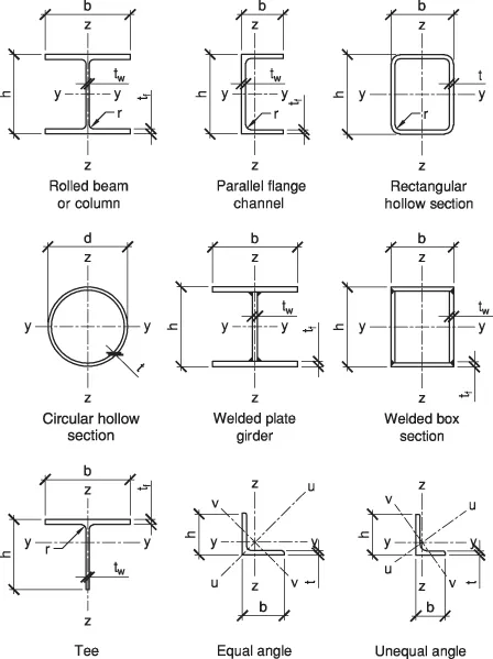
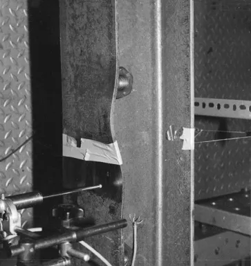
Figure 14.2 shows a short UC section after it has been tested as a column. Considerable deformation of the cross-section is evident with the flanges being displaced out of their original flat shape. The web, on the other hand, appears to be comparatively undeformed. The buckling has therefore been confined to certain plate elements and has not resulted in any overall lateral deformation of the member (i.e. its centroidal axis has not deflected). In the particular example of Figure 14.2, local buckling did not develop significantly until well after the column had sustained its yield load, equal to the product of its cross-sectional area and its material strength. Local buckling did not prevent attainment of the yield load because the proportions of the web and flange plates are sufficiently stocky. The fact that the local buckling appeared in the flanges before the web is due to the former being the more slender.
Figure 14.2 Local buckling of column flange
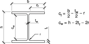
Terms such as stocky (or compact) and slender are used to describe the proportions of the individual plate elements of structural sections, based on their susceptibility to local buckling. The most important governing property is the ratio of plate width to plate thickness, λp, referred to as the c / t ratio in Eurocode 3 or, more generally, the b / t ratio. Other influential factors are material strength, the stress system to which the plate is subjected and the support conditions provided. Note that the Eurocode width to thickness (c / t) ratios are based on the flat widths only of the plated elements, e.g. the flat width between the ends of the root radii for the web of an I-section, or the flat width from the end of the root radius to the tip of the flange for an outstand element, as illustrated in Figure 14.3.
Figure 14.3 Definition of flat element widths cf and cw
Although the rigorous treatment of plate buckling is a complex topic,1,2 it is possible to design safely and, in most cases, economically with no direct consideration of the subject. For example, the properties of the majority of standard hot-rolled sections have been selected such that local buckling effects are unlikely to affect significantly their load-carrying capacity when used as beams or columns. Greater care is, however, necessary when using fabricated sections, for which the proportions are under the direct control of the designer. Also, cold-formed sections are often proportioned such that local buckling effects must be accounted for, as described in Chapter 24.
14.2 Cross-Sectional Dimensions and Moment-Rotation Behaviour
Figure 14.4 shows a rectangular box section subject to major axis bending and illustrates the elastic stress distributions in the flanges and webs. The plate slenderness ratios for the flanges and webs are cf / tf and cw / tw, respectively. If the beam is subject to equal and opposite end moments M, Figure 14.5 shows, in a qualitative manner, different forms of relationship between M and the corresponding rotation θ.
Figure 14.4 Rectangular box section in bending
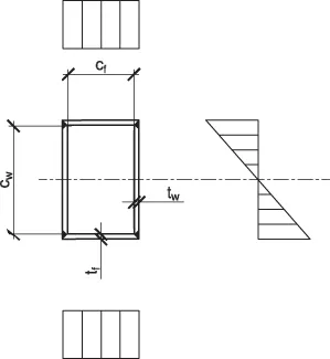
Figure 14.5 Behaviour in bending of different classes of section
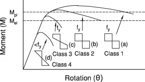
Assuming cw / tw to be such that local buckling of the webs does not occur, which of the four different forms of response given in Figure 14.5 applies depends on the compression flange slenderness cf / tf. The four cases are defined as:
1. cf / tf ≤ λp1, the full plastic moment capacity Mpl is attained and maintained for large rotations and the member is suitable for plastic design – Class 1 cross-section
2. λp1 < cf / tf ≤ λp2, the full plastic moment capacity Mpl is attained but is only maintained for small rotations and the member is suitable for elastic design using its full capacity – Class 2 cross-section
3. λp2 < cf / tf ≤ λp3, the elastic moment capacity Mel (but not Mpl) is attained and the member is suitable for elastic design using this limited capacity – Class 3 cross-section
4. λp3 ≤ cf / tf, local buckling limits moment capacity to less than Mel – Class 4 (slender) cross-section.
The relationship between moment capacity Mc and compression flange slenderness cf / tf indicating the various λp limits is illustrated diagrammatically in Figure 14.6. In the above discussion, classification of the section has been...
Table of contents
- Cover
- Title page
- Copyright page
- Introduction to the seventh edition
- Contributors
- INTRODUCTION
- DESIGN SYNTHESIS
- APPLIED METALLURGY
- ANALYSIS
- ELEMENT DESIGN
- CONNECTION DESIGN
- FOUNDATIONS
- CONSTRUCTION
- Appendix
- Index
Frequently asked questions
Yes, you can cancel anytime from the Subscription tab in your account settings on the Perlego website. Your subscription will stay active until the end of your current billing period. Learn how to cancel your subscription
No, books cannot be downloaded as external files, such as PDFs, for use outside of Perlego. However, you can download books within the Perlego app for offline reading on mobile or tablet. Learn how to download books offline
Perlego offers two plans: Essential and Complete
- Essential is ideal for learners and professionals who enjoy exploring a wide range of subjects. Access the Essential Library with 800,000+ trusted titles and best-sellers across business, personal growth, and the humanities. Includes unlimited reading time and Standard Read Aloud voice.
- Complete: Perfect for advanced learners and researchers needing full, unrestricted access. Unlock 1.5M+ books across hundreds of subjects, including academic and specialized titles. The Complete Plan also includes advanced features like Premium Read Aloud and Research Assistant.
We are an online textbook subscription service, where you can get access to an entire online library for less than the price of a single book per month. With over 1.5 million books across 990+ topics, we’ve got you covered! Learn about our mission
Look out for the read-aloud symbol on your next book to see if you can listen to it. The read-aloud tool reads text aloud for you, highlighting the text as it is being read. You can pause it, speed it up and slow it down. Learn more about Read Aloud
Yes! You can use the Perlego app on both iOS and Android devices to read anytime, anywhere — even offline. Perfect for commutes or when you’re on the go.
Please note we cannot support devices running on iOS 13 and Android 7 or earlier. Learn more about using the app
Please note we cannot support devices running on iOS 13 and Android 7 or earlier. Learn more about using the app
Yes, you can access Steel Designers' Manual by Buick Davison, Graham W. Owens, Buick Davison,Graham W. Owens in PDF and/or ePUB format, as well as other popular books in Technology & Engineering & Civil Engineering. We have over 1.5 million books available in our catalogue for you to explore.