![]()
Chapter 1
General Points
1.1. Microwave photonic links
All signals generated or observed due to human activity (measurement of different physical values, remote control, files, sounds, images, etc.) can be transformed into analog electrical signals. These electrical signals can be processed or transmitted as they are, but in most cases they are digitized beforehand. Once digitized, these signals have different forms regarding the digital coding or error-correcting algorithms used and protocols employed in the transmission systems. To be processed or transmitted, these analog or digital signals can use different mediums.
If the transmission is performed via metallic lines or cables, digital signals directly enter these lines or they modulate more or less complex subcarriers (ADSL, Ethernet).
If transmission occurs with a radiowave, a high-frequency carrier must be available. Due to the congestion of the wireless spectrum, carriers are now principally microwaves, i.e. with frequencies of 1 to 100 GHz (GSM, UMTS, Wi-Fi, Wimax, etc.). Wireless transmission can also be performed by very short pulses having a wide spectrum range, including the microwave spectrum, or these pulses can modulate a carrier in the millimeter wave spectrum. This technique is known as ultra-wideband (UWB) [YAO 09].
If transmission is via fiber optics, digital signals modulate one or several optical carriers (amplitude or soliton modulation), which are themselves transmitted over hundreds of kilometers on optical fibers. This is the case for all passive optical networks (PON) and their different transmission protocols [LEC 97].
From these definitions, the distinctive feature of microwave photonic links is to transmit a microwave signal analogically or for it be digitally modulated. This microwave signal is transferred to an optical carrier, which is guided with minimum loss by an optical fiber. The microwave signal is then picked up by a photodetector at the end of the fiber.
One of the first applications of microwave optical links was the distribution of the microwave carrier in radar or radio-astronomy systems comprising offset aerials or active phased-array antennas, which benefited from the low weight and low volume of the fiber optics [COX 97, DEC 98].
Another important area comprises all radio over fiber (RoF) applications consisting of the extension of wireless networks using microwaves or UWB waves. The optical tunnels produced are capable of reaching all rooms or buildings of a company, university, or diverse institutions or all the rooms of a house whilst benefiting from the very low loss associated with fiber optics [FRI 02].
Amongst the applications of RoF, a promising domain is in the connection of internet transmission networks to the home. These connections are increasingly popular with ever-increasing speeds (1 Gb/s) due to fiber optics reaching households (fiber to the home or FTTH), whereby the house itself becomes a high-speed local network. In this local network, the signal distribution in each room is achieved by a 60 GHz millimeter-wave (wireless personal area network or WPAN), which stays confined in the room due to the extremely fast attenuation at this frequency. All rooms are linked to each other by a network of passive fiber optics which extends the millimeter-wave UWB signal throughout the whole house (ultra broadband wireless home area network or UBB-WHAN). Examples of millimeter-wave over optical transmissions are presented in [CHU 07; KIM 04; WEI 08] and a demonstration of a UBB-WHAN with an up and down link is described in [HUC 08].
The length of a link ranges from 10 m to 1 km allowing several fiber types to be used (single mode or multimode, silica or plastic) and several optical wavelengths ranging from 0.6 to 1.55 µm. The light undergoes intensity modulation; the signal is received via photodetection. In just a few years rates have risen from around 10 Mb/s on carriers of a few gigahertz to rates of 1 or 10 Gb/s on 60 GHz for microwave carriers.
A microwave photonic link is constituted of three parts:
– a coherent light source: a laser that emits an optical carrier, the intensity of which is directly modulated inside the laser or externally by an optical modulator. In the case of external modulation, the amplitude modulation is performed by a Mach-Zehnder or an electro-absorption modulator;
– the modulated light is then transported by single or multi-mode optical fiber [GOM 08; KOO 08] made of silica or plastic [KOI 06]. This part may include an optical amplification;
– the modulated light is finally photodetected in a photodetector consisting of a photodiode or a phototransistor.
After some deliberation regarding coherent and incoherent optical links [HAL 82], the solution finally adopted for these links was “intensity modulation (IM) direct detection (DD)”. As this is recalled in [COX 06], in this type of link, the depth of optical modulation is sufficiently weak that we can initially use small signal or linear techniques for each aspect. Because the signals applied to links or extracted from them are in microwaves, the variables characterizing these systems are S-parameters, gains, and noise factors. Also nonlinearities, and hence intermodulation produced by each component on the signal introduced in the link must be considered. The combination of these different characteristics leads to the notion of interference-free dynamic range (IFDR). This shall be evaluated regarding the properties of each element in the chapters concerning overall performances of such links.
As a link includes electrical-to-optical, optical-to-electrical, and even optical-to-optical transducers, each of the magnitudes in terms of S-parameters, gains, and noise factors should be presented in the form of optomicrowave magnitudes. This aspect forces harmonization of notions from the optical, optoelectronic, and microwave disciplines. This is described in Chapter 5.
The term used initially to describe these links was “microwave optical links”. However, the techniques used have gradually distanced themselves from proper optical and optoelectronic techniques so that the more specific term “microwave photonic links” has been progressively used [SEE 02].
1.2. Link description
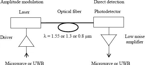
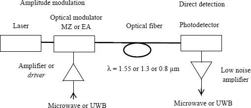
Figures 1.1 and 1.2 represent a general diagram of an IM-DD microwave optical link.
Figure 1.1 represents a direct modulation link. A laser emits a light of wavelength 0.8 or 1.3 or 1.55 µm, this laser is modulated by a microwave signal (which is possibly itself modulated) through a driver circuit. The modulated light enters an optical fiber coupled to a photodetector that detects the microwave modulation signal. The optical modulation can have an amplitude, frequency, and phase. However, direct photodetection detects only the modulation in amplitude. The detected microwave signal is then amplified by a low-noise amplifier.
Figure 1.2 represents an external modulation link. This time, a light emitted from a laser is injected into a Mach-Zehnder or electro-absorption amplitude modulator. In this case, microwave modulation is also applied to the modulator through a driver circuit.
After passing into an optical fiber, the optical intensity modulation only is detected via a photodetector. As in the previous diagram, the detected microwave signal is amplified in a low-noise amplifier.
1.3. Signal to transmit
1.3.1. Microwave signal
The first type of transmitted signal is a signal that constitutes a microwave frequency reference. It can be used in offset aerial systems or active phased-array antenna. After its reflection from a moving object, the microwave signal emitted from an antenna can shift in frequency (Doppler modulation) and it is the spectral purity of the microwave that determines the minimum observed frequency shift and therefore, the minimum relative speed of the moving object. The spectral purity and degradation after transmission of the microwave by optical links must be watched closely to distinguish the frequency shift.
1.3.2. Microwave carrier for a digital signal
If the microwave signal serves as a carrier for a digital signal this carrier is previously modulated. All the modulation techniques normally used, such as amplitude, frequency, phase, OFDM, and combined amplitude-phase modulation (QAM), or more complex techniques can be considered, such as those used in GSM, GPRS, EDGE, and UMTS for mobile telephones or such as Bluetooth, Wi-Fi and Wimax for data tran...