![]()
1
Electricity Generation from Wind Energy
There is now general acceptance that the burning of fossil fuels is having a significant influence on the global climate. Effective mitigation of climate change will require deep reductions in greenhouse gas emissions, with UK estimates of a 60–80% cut being necessary by 2050 (Stern Review, UK HM Treasury, 2006). The electricity system is viewed as being easier to transfer to low-carbon energy sources than more challenging sectors of the economy such as surface and air transport and domestic heating. Hence the use of cost-effective and reliable low-carbon electricity generation sources, in addition to demand-side measures, is becoming an important objective of energy policy in many countries (EWEA, 2006; AWEA, 2007).
Over the past few years, wind energy has shown the fastest rate of growth of any form of electricity generation with its development stimulated by concerns of national policy makers over climate change, energy diversity and security of supply.
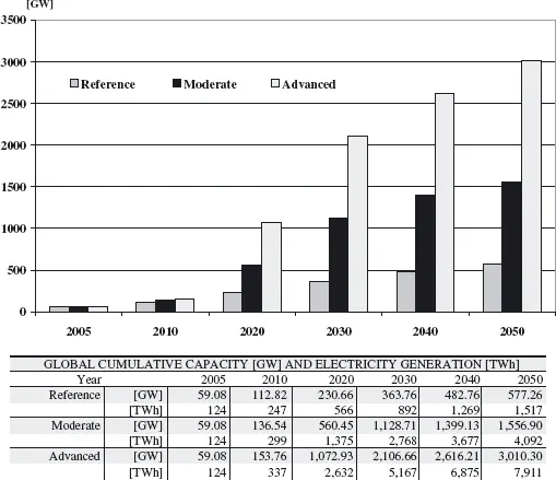
Figure 1.1 shows the global cumulative wind power capacity worldwide (GWEC, 2006). In this figure, the ‘Reference’ scenario is based on the projection in the 2004 World Energy Outlook report from the International Energy Agency (IEA). This projects the growth of all renewables including wind power, up to 2030. The ‘Moderate’ scenario takes into account all policy measures to support renewable energy either under way or planned worldwide. The ‘Advanced’ scenario makes the assumption that all policy options are in favour of wind power, and the political will is there to carry them out.
1.1 Wind Farms
Numerous wind farm projects are being constructed around the globe with both offshore and onshore developments in Europe and primarily large onshore developments in North America. Usually, sites are preselected based on general information of wind speeds provided by a wind atlas, which is then validated with local measurements. The local wind resource is monitored for 1 year, or more, before the project is approved and the wind turbines installed.
Onshore turbine installations are frequently in upland terrain to exploit the higher wind speeds. However, wind farm permitting and siting onshore can be difficult as high wind-speed sites are often of high visual amenity value and environmentally sensitive.
Offshore development, particularly of larger wind farms, generally takes place more than 5 km from land to reduce environmental impact. The advantages of offshore wind farms include reduced visual intrusion and acoustic noise impact and also lower wind turbulence with higher average wind speeds.
Table 1.1 Wind turbine applications (Elliot, 2002)
| | |
| | |
- Autonomous remote applica- tions (e.g. battery charging, water pumping, telecom sites)
| | - Onshore and offshore wind generation
|
The obvious disadvantages are the higher costs of constructing and operating wind turbines offshore, and the longer power cables that must be used to connect the wind farm to the terrestrial power grid.
In general, the areas of good wind energy resource are found far from population centres and new transmission circuits are needed to connect the wind farms into the main power grid. For example, it is estimated that in Germany, approximately 1400 km of additional high-voltage and extra-high-voltage lines will be required over the next 10 years to connect new wind farms (Deutsche Energie-Agentur GmbH, 2005).
Smaller wind turbines may also be used for rural electrification with applications including village power systems and stand-alone wind systems for hospitals, homes and community centres (Elliot, 2002).
Table 1.1 illustrates typical wind turbine ratings according to their application.
1.2 Wind Energy-generating Systems
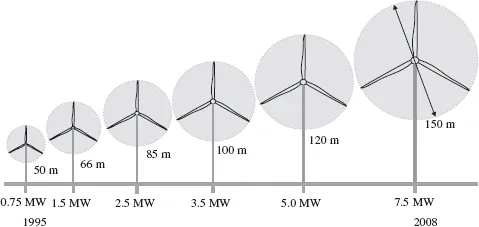
Wind energy technology has evolved rapidly over the last three decades (Figure 1.2) with increasing rotor diameters and the use of sophisticated power electronics to allow operation at variable rotor speed.
1.2.1 Wind Turbines
Wind turbines produce electricity by using the power of the wind to drive an electrical generator. Wind passes over the blades, generating lift and exerting a turning force. The rotating blades turn a shaft inside the nacelle, which goes into a gearbox. The gearbox increases the rotational speed to that which is appropriate for the generator, which uses magnetic fields to convert the rotational energy into electrical energy. The power output goes to a transformer, which converts the electricity from the generator at around 700 V to the appropriate voltage for the power collection system, typically 33 kV.
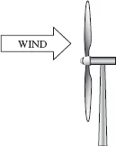
A wind turbine extracts kinetic energy from the swept area of the blades (Figure 1.3). The power in the airflow is given by (Manwell et al., 2002; Burton et al., 2001):
where
ρ = air density (approximately 1.225 kg m−3) A = swept area of rotor, m2
ν = upwind free wind speed, m s−1.
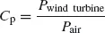
Although Eq. (1.1) gives the power available in the wind the power transferred to the wind turbine rotor is reduced by the power coefficient, Cp:
A maximum value of Cp is defined by the Betz limit, which states that a turbine can never extract more than 59.3% of the power from an air stream. In reality, wind turbine rotors have maximum Cp values in the range 25–45%.
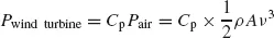
It is also conventional to define a tip-speed ratio, λ,as
where
ω = rotational speed of rotor
R = radius to tip of rotor
ν = upwind free wind speed, m s−1.
The tip-speed ratio, λ, and the power coefficient, Cp, are dimensionless and so can be used to describe the performance of any size of wind turbine rotor. Figure 1.4 shows that the maximum power coefficient is only achieved at a single tip-speed ratio and for a fixed rotational speed of the wind turbine this only occurs at a single wind speed. Hence, one argument for operating a wind turbine at variable rotational speed is that it is possible to operate at maximum Cp over a range of wind speeds.
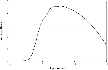
The power output of a wind turbine at various wind speeds is conventionally described by its power curve. The power curve gives the steady-state electrical power output as a function of the wind speed at the hub height and is generally measured using 10 min average data. An example of a power curve is given in Figure 1.5.
The power curve has three key points on the velocity scale:
- Cut-in wind speed – the minimum wind speed at which the machine will deliver useful power.
- Rated wind speed – the wind speed at which rated power is obtained (rated power is generally the maximum power output of the electrical generator).
- Cut-out wind speed – the maximum wind speed at which the turbine is allowed to deliver power (usually limited by engineering loads and safety constraints).
Below the cut-in speed, of about 5 m s−1, the wind turbine remains shut down as the speed of the wind is too low for useful energy production. Then, once in operation, the power output increases following a broadly cubic relationship with wind speed (although modified by the variation in Cp) until rated wind speed is reached. Above rated wind speed the aerodynamic rotor is arranged to limit the mechanical power extracted from the wind and so reduce the mechanical loads on the drive train. Then at very high wind speeds the turbine is shut down.
The choice of cut-in, rated and cut-out wind speed is made by the wind turbine designer who, for typical wind conditions, will try to balance obtaining maximum energy extraction with controlling the mechanical loads (and hence the capital cost) of the turbine. For a mean annual site wind speed Vm of 8ms−1typical values will be approximately (Fox et al., 2007):
- cut-in wind speed: 5 m s−1, 0.6 Vm
- rated wind speed: 12–14ms−1,1.5–1.75 Vm
- cut-out wind speed: 25 m s−1, 3Vm.
Power curves for existing machines can normally be obtained from the turbine manufacturer. They are found by field measurements, where an anemometer is placed on a mast reasonably close to the wind turbine, not on the turbine itself or too close to it, since the turbine may create turbulence and make wind speed measurements unreliable.
1.2.2 Wind Turbine Architectures
There are a large number of choices of architecture available to the designer of a wind turbine and, over the years, most of these have been explored (Ackermann, 2005; Heier, 2006). However, commercial designs for electricity generation have now converged to horizontal axis, three-bladed, upwind turbines. The largest machines tend to operate at variable speed whereas smaller, simpler turbines are of fixed speed.
Modern electricity-generating wind turbines now use three-bladed upwind rotors, although two-bladed, and even one-bladed, rotors were used in earlier commercial turbines. Reducing the number of blades means that the rotor has to operate at a higher rotational speed in order to extract the wind energy passing through the rotor disk. Although a high rotor speed is attractive in that it reduces the gearbox ratio required, a high blade tip speed leads to increased aerodynamic noise and increased blade drag losses. Most importantly, three-bladed rotors are visually more pleasing than other designs and so these are now always used on large electricity-generating turbines.
1.2.2.1 Fixed-speed Wind Turbines
Fixed-speed wind turbines are electrically fairly simple devices consisting of an aerodynamic rotor driving a low-speed shaft, a gearbox, a high-speed shaft and an induction (sometimes known as asynchronous) generator. From the electrical system viewpoint they are perhaps best considered as large fan drives with torque applied to the low-speed shaft from the wind flow.
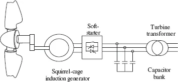
Figure 1.6 illustrates the configuration of a fixed-speed wind turbine (Holdsworth et al., 2003; Akhmatov, 2007). It consists of a squirrel-cage induction generator coupled to the power system through a turbine transformer. The generator operating slip changes slightly as the operating power level changes and the rotational speed is therefore not entirely constant. However, because the operating slip variation is generally less than 1%, this type of wind generation is normally referred to as fixed speed.
Squirrel-cage induction machines consume reactive power and so it is conventional to provide power factor correction capacitors at each wind turbine. The function of the soft-starter unit is to build up the magnetic flux slowly and so minimize transient currents during energization of the generator. Also, by applying the network voltage slowly to the generator, once energized, it brings the drive train slowly to its operating rotational speed.
1.2.2.2 Variable-speed Wind Turbines
As the size of wind turbines has become larger, the technology has switched from fixed speed to variable speed. The drivers behind these developments are mainly the ability to comply with Grid Code connection requirements and the reduction in mechanical loads achieved with variable-speed operation. Currently the most common variable-speed wind turbine configurations are as follows:
- doubly fed induction generator (DFIG) wind turbine
- fully rated converter (FRC) wind turbine based on a synchronous or induction generator.
Doubly Fed Induction Generator (DFIG) Wind Turbine
A typical configuration of a DFIG wind turbine is shown schematically in Figure 1.7. It uses a wound-rotor induction generator with slip rings to take current into or out of the rotor winding and variable-speed operation is obtained by injecting a controllable voltage into the rotor at slip frequency (Muller¨et al., 2002; Holdsworth et al., 2003). The rotor winding is fed through a varia...