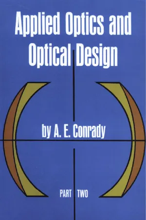
Applied Optics and Optical Design, Part Two
eBook - ePub

Applied Optics and Optical Design, Part Two

  1. 352 pages
  2. English
  3. ePUB (mobile friendly)
  4. Available on iOS & Android
eBook - ePub

Applied Optics and Optical Design, Part Two

Book details
Book preview
Table of contents
Citations

About This Book

"For the optical engineer it is an indispensable work." ā€” Journal, Optical Society of America
"As a practical guide this book has no rival." ā€” Transactions, Optical Society
"A noteworthy contribution, " ā€” Nature (London)
This two-volume paperback republication of A. E. Conrady's classic work presents his complete system of optical design. The only work of its kind in English, this set leads the reader step by step from the fundamental concepts of geometrical and physical optics up to the point where he can design the simpler optical systems without aid. It remains the only detailed work on the subject written with the needs of the practical designer and the self-taught constantly in mind. For most of the text, no mathematics above trigonometry is needed; occasional sections require some calculus and analytical geometry.
Part I covers all ordinary ray-tracing methods, together with the complete theory of primary aberrations and as much of higher aberration as is needed for the design of telescopes, low-power microscopes and simple optical systems. Chapters: Fundamental Equations, Spherical Aberration, Physical Aspect of Optical Images, Chromatic Aberration, Design of Achromatic Object-Glasses, Extra-Axial Image Points, The Optical Sine Theorem, Trigonometric Tracing of Oblique Pencils, General Theory of Perfect Optical Systems, and Ordinary Eyepieces.
Part II extends the coverage to the systematic study and design of practically all types of optical systems, with special attention to high-power microscope objectives and anastigmatic photographic objectives. Edited and completed from the author's manuscript by Rudolf Kingslake, Director of Optical Design, Eastman Kodak Company. Chapters: Additional Solutions by the Thin-Lens Method, Optical Path Differences, Optical Path Differences at an Axial Image Point, Optical Tolerances, Chromatic Aberration as an Optical Path Difference, The Matching Principle and the Design of Microscope Objectives, Primary Aberrations of Oblique Pencils, Analytical Solutions for Simple Systems with Remote Stop, Symmetrical Photographic Objectives, and Unsymmetrical Photographic Objectives.

Frequently asked questions

Simply head over to the account section in settings and click on ā€œCancel Subscriptionā€ - itā€™s as simple as that. After you cancel, your membership will stay active for the remainder of the time youā€™ve paid for. Learn more here.
At the moment all of our mobile-responsive ePub books are available to download via the app. Most of our PDFs are also available to download and we're working on making the final remaining ones downloadable now. Learn more here.
Both plans give you full access to the library and all of Perlegoā€™s features. The only differences are the price and subscription period: With the annual plan youā€™ll save around 30% compared to 12 months on the monthly plan.
We are an online textbook subscription service, where you can get access to an entire online library for less than the price of a single book per month. With over 1 million books across 1000+ topics, weā€™ve got you covered! Learn more here.
Look out for the read-aloud symbol on your next book to see if you can listen to it. The read-aloud tool reads text aloud for you, highlighting the text as it is being read. You can pause it, speed it up and slow it down. Learn more here.
Yes, you can access Applied Optics and Optical Design, Part Two by A. E. Conrady in PDF and/or ePUB format, as well as other popular books in Sciences physiques & Physique. We have over one million books available in our catalogue for you to explore.

Information

Year
2014
ISBN
9780486162621

CHAPTER XI

ADDITIONAL SOLUTIONS BY THE THIN-LENS METHOD

(AXIAL CORRECTION ONLY)
[82] IT was shown in Chapters II, V, VI, and VII of Part I that approximate solutions for reasonably thin lens systems satisfying certain conditions can be secured with very little trouble by the simple algebraic formulae which neglect the thicknesses entirely, and that these rough solutions can then be readily corrected trigonometrically by the differential methods which were given for that indispensible final operation.
Our present purpose is not to supersede or modify those methods, but to make valuable additions to them and to obtain an extended survey of all the possibilities and limitations of thin systems by a more complete and general discussion of the equations.
The procedure consists in first fixing the focal length fā€² of the system, which may necessitate a simple preliminary calculation by the thin-lens paraxial equations. As some type of achromatism is nearly always required, the next step calls for the determination of the strength or net curvature of the component lenses which will secure this. For the most usual case of complete achromatism of a combination of two thin lenses the formulae are
image
The spherical aberration and the sagittal coma for central passage of the oblique pencils through the thin system are then given for any distance of the object and for any bending of the constituent lenses by the equations
image
The G-sums of the individual thin lenses can be worked out in two interchangeable forms to be referred to as the ā€˜originalā€™ (i.e. as first proved) and the ā€˜alternativeā€™ (as subsequently transformed) G-sum; they are
image
The signs of the terms, and especially the changes of sign in the ā€˜originalā€™ and ā€˜alternativeā€™ sums must of course be most carefully observed. The total or net curvature of a particular lens c = c1 āˆ’ c2 is connected with its focal length by c(N āˆ’ 1) = 1/fā€². The individual curvatures of the left and right surfaces of the lens are c1 = 1/r1 and c2 = 1/r2 respectively. The reciprocals of the left- and right-hand external intersection lengths of the lens standing in air are Ļ…1 = 1/l1 and Ļ…ā€²2 = 1/lā€²2; hence by the thin-lens equations Ļ…ā€²2 = Ļ…1 +1/fā€² = Ļ…1 + c (N āˆ’1). The eight G-values are pure functions of N with the explicit values (Part I, pages 95 and 324):
image
; G4 = (N + 2)(N āˆ’1)/2N; G5 = 2(N2 āˆ’ 1)/N; G6 = (3N + 2)(Nāˆ’1)/2N; G7 = (2N + 1)(N āˆ’ 1)/2N;
image
. A table of their numerical values and their logs was given in Part I, page 513. Since all the G-values have (N āˆ’ 1) as one factor combined with other very simple terms, there are many simple relations between them, and as these are useful in certain transformations, we shall collect the principal relations here:
image
In Part I we used the TL equations exclusively for the solution of definite problems, and the complete form in which they are stated above was then the most convenient one and fitted in with the trigonometrical correction. In the present chapter one of our chief aims will be to include the object distance expressed by Ļ…1 or Ļ…ā€²2 as one of the variables, and the lā€²k2 in the outside factor of the G-sums in the equations for LAā€² would then become objectionable because lā€²k necessarily would vary when Ļ…1 or Ļ…ā€²2 are treated as variable. We shall evade this complication by omitting the outside factors in the equation for both LAā€² and Comaā€²s and by discussing simply the value of the G-sums. This is justified firstly by the fact that interest is nearly always limited to zero-value of both aberrations or, at any rate, to low values of the order of the tolerances, for it is obvious that the aberrations can only become zero or small when the G-sums are zero or small. But there are very good additional argumentsā€”from our present point of viewā€”against the lā€²k2 in the expression for LAā€²: this term arose out of the transfer of the contributions of individual surfaces to the final image position by the law of longitudinal magnification, and it is thus closely associated with the misleading changes in magnitude of longitudinal spherical aberration according to the convergence of pencils. This becomes clear if we convert LAā€² into the more reliable measure of angular aberration by (10)****: AAā€²p = LAā€²pĀ·uā€²/lā€². For our present equation uā€² and lā€² must be given the suffix k, and uā€²k must be put equal to SA/lā€²k. Hence we can convert our equation for LAā€² into A Aā€² by the factor SA/lā€²k2 and find, for any thin system,
image
which is simply p...

Table of contents

  1. Cover
  2. Title Page
  3. Copyright Page
  4. Dedication
  5. Foreword
  6. Editor
  7. Contents
  8. XI. Additional Solutions by the Thin-Lens Method
  9. XII. Optical Path Differences
  10. XIII. Optical Path Differences at an Axial Image Point
  11. XIV. Optical Tolerances
  12. XV. Chromatic Aberration as an Optical Path Difference
  13. XVI. The Matching Principle and the Design of Microscope Objectives
  14. XVII. Primary Aberrations of Oblique Pencils
  15. XVIII. Analytical Solutions for Simple Systems With Remote Stop
  16. XIX. Symmetrical Photographic Objectives
  17. XX. Unsymmetrical Photographic Objectives
  18. Appendices
  19. Index