![]()
Chapter 1
Introduction
1.1 ROLE OF VEGETATION IN CIVIL ENGINEERING
For many centuries, living plants and dead wood had been used to reinforce soil slopes, embankments, foundations (e.g., timber piles) and earthen retaining walls such as those in ancient China (Smith and Snow, 2008) and ancient Rome (Partov et al., 2016). The design of these green reinforcement technologies was essentially empirical. As the world became increasingly industrialised, concrete and steel replaced timbers as the key materials in various types of infrastructural development and construction projects, including the improvement of slope stability. The mechanical properties of these man-made materials are highly controllable and predictable, and hence, they offer engineers and designers a better sense of safety and security in general. Nowadays, however, people seek for more environmentally friendly and green solutions to many engineering problems. The desire of the public to create a sustainable world for future generations has gradually motivated governments and engineers to rediscover vegetation as an engineering material. Soil bioengineering can potentially offer an environmentally friendly, cost-effective and aesthetically pleasant solution for enhancing the stability of shallow soil slopes and controlling the surface erosion resulting from blowing winds and moving waters.
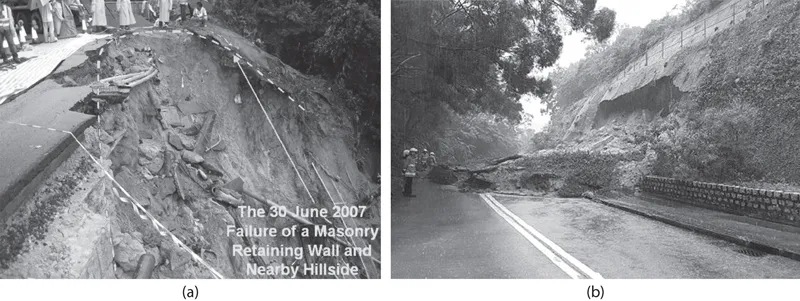
In the tropical and subtropical regions of the world, shallow slopes (i.e., those less than 2 m deep) often fail because of the short-duration but intensive rainfalls (GEO, 2011; Ng et al., 2016a). Stone walls and chunam covers (Figure 1.1) are commonly used to protect slopes in some parts of the world, including Hong Kong. However, it has become evident that stone walls and chunam covers could not maintain the slope stability, and these methods are in fact not environmentally friendly, not to mention aesthetically unpleasant. Although vegetation has been used empirically for decades in slope protection, it is mainly done for aesthetic purposes (Coppin and Richards, 1990). In fact, the function of vegetation has not yet been fully integrated into the analysis and design of slopes in a scientific manner.
A well-recognised effect of roots on slope stability is their mechanical reinforcements in shallow soil slopes (Wu et al., 1979; Pollen and Simon, 2005). Plant roots, which can sustain tension, occupy the space of soil pore and increase the tensile strength and shear strength of soil–root composites. In the past decades, mechanical root reinforcement has been extensively quantified, both experimentally and analytically (Wu et al., 1979; Pollen and Simon, 2005; Fan and Su, 2008; Jotisankasa and Taworn, 2016). This mechanical effect can be readily included in slope stabilisation calculations (Greenwood et al., 2004; Genet et al., 2010; Mao et al., 2014). How much mechanical reinforcement contributes to soil shear strength depends strongly not only on the biomechanical properties of roots (i.e., root tensile strength and Young’s modulus) but also on the root architecture and the amount of roots in the rooted zone (Pollen and Simon, 2005; Ng et al., 2016a; Boldrin et al., 2017a).
Figure 1.1 Traditional slope failure in Hong Kong: (a) a stone wall (Repulse Bay Road; 30 June 2007) and (b) a chunam cover (South Lantau Road; 7 September 2016). The two photos are provided by the Geotechnical Engineering Office, Civil Engineering and Development Department, Hong Kong SAR.
In addition to providing mechanical reinforcement, living roots induce soil suction (or negative pore water pressure) through root water uptake via transpiration (Ng et al., 2013; Garg et al., 2015b; Leung et al., 2015a). Soil suction can also be induced or further increased by evaporation from the soil surface. The combined physical processes of transpiration and evaporation are referred to as evapotranspiration (ET) (Gardner, 1960). This further enhances the shear strength of soil and more importantly helps to reduce water permeability and infiltration (Ng and Menzies, 2007; Leung and Ng, 2013a). The key to applying this green engineering technique successfully is to first understand the fundamentals of unsaturated soil mechanics and soil–plant–atmosphere interactions, which are interdisciplinary subjects involving atmospheric science, soil science, botany and geotechnical engineering.
1.2 FUNDAMENTALS OF UNSATURATED SOIL MECHANICS
To improve our understanding of soil–plant–atmosphere interactions, the relevant theories of unsaturated soil mechanics are introduced in this section. Soil suction is defined as the free energy state of soil water (Edlefsen and Anderson, 1943; Richards, 1965). According to the thermodynamic theory, the total suction ψT in soil is related to the partial pressure of pore–water vapour (Aitchison, 1965) and expressed as follows:
| (1.1) |
where R is the universal gas constant, Ta is the absolute temperature, ωv is the molecular mass of water, υwo is the specific volume of water, uv is the partial pressure of pore–water vapour, uv1 is the partial vapour pressure above the soil water and uvo is the saturation pressure of pore–water vapour over a flat surface of pure water at the same temperature (Fredlund and Rahardjo, 1993). According to Eq. (1.1), the total soil suction is composed of soil matric suction (the first term on the right-hand side of the equation) and osmotic suction (the second term on the right-hand side of the equation).
Up to now, soil–plant–atmosphere interactions have not been taken into account in the design of geotechnical infrastructure, mainly due to limited understanding of the complex mechanisms involved. Plants would reduce the soil water content, and the corresponding increase in suction would lead to changes in both the shear strength and water permeability of the unsaturated soil. The effects of root water uptake on soil shear strength and water permeability are referred as ‘hydrological effects’ (Ng, 2017).
For simplicity, the shear strength of an unsaturated soil, τf, may be expressed in terms of water content and soil matric suction, as follows (Vanapalli et al., 1996):
| (1.2) |
where c′ is the effective cohesion; σn is the normal stress; ua and uw are the pore–air pressure and pore–water pressure, respectively; ϕ′ is the effective friction angle; θ is the volumetric water content; θs is the saturated volumetric water content and θr is the residual water content. The difference between ua and uw (i.e., ua − uw) is called ma...