eBook - ePub
Sustainable Material Forming and Joining
- 456 pages
- English
- ePUB (mobile friendly)
- Available on iOS & Android
eBook - ePub
Sustainable Material Forming and Joining
About this book
The main objective of the book is to expose readers to the basics of sustainable material forming and joining technologies, and to discuss the relationship between conventional and sustainable processes. It also provides case studies for sustainable issues in material forming and joining processes, workouts for converting conventional processes to green processes, and highlights the importance of awareness on sustainable and green manufacturing through education. The book will include green and sustainability concepts in material forming like bulk forming and sheet forming emphasizing hot forming, materials development, lubrication, and minimizing defects.
Key Features
- Conceptualizes green and sustainability issues towards efficient material forming and joining
- Addresses important aspects of sustainable manufacturing by forming operations
- Presents comparison between traditional and sustainable manufacturing processes
- Includes practical case studies from industry experts
- Discusses green and sustainability concepts in material forming like bulk forming and sheet forming emphasizing hot forming, materials development, lubrication, and minimizing defects
Tools to learn more effectively

Saving Books

Keyword Search

Annotating Text

Listen to it instead
Information
CHAPTER 1
Introduction to Sustainable Manufacturing Processes
IIT Guwahati
Ohio University
CONTENTS
1.1 Conventional Manufacturing Processes
1.1.1 Metal Forming Processes
1.1.2 Joining Processes
1.2 Sustainable Manufacturing
1.3 Sustainable Material Forming and Joining
1.4 Computer-Aided Engineering Analyses
1.5 Summary
References
1.1 CONVENTIONAL MANUFACTURING PROCESSES
Casting, forming, joining, and machining have been the four well-known manufacturing processes to mankind for many decades. Casting has been used to make raw materials since the discovery of structural metals such as copper, iron, etc. In this process, solidified metal blocks, in varied dimensions, are manufactured through melting and solidification. Sand casting, investment casting, die casting, and centrifugal casting are typical examples of casting processes. The solidified metal blocks are then processed to make usable components. In metal (material) forming, plastic deformation has been used to make usable components. A permanent shape is given to the material by using rigid tools. Rolling, forging, extrusion, wire drawing, sheet stamping, shearing, spinning, and tube forming are some of the typical examples of material forming processes. Joining is used to assemble raw materials or fabricated components, either permanently or temporarily, depending on the requirements of application. Welding, adhesive bonding, fastening, and riveting are some of the joining processes used predominantly. Joining involves providing heat and/or pressure to the materials for assembly. Hence, plastic deformation is involved in some of the joining processes. Machining involves removing of material to attain the final shape of the product. Some of the typical machining processes are turning, drilling, milling, shaping, planning, broaching, sawing, etc. Although defined separately, these processes are often combined to manufacture engineering goods. This chapter introduces conventional material forming and joining processes, thus highlighting the importance of sustainability in manufacturing. Finally, some of the sustainable material forming and joining processes have been discussed with some research contributions.
1.1.1 Metal Forming Processes
The metal forming processes are divided into the following two processes: bulk forming and sheet forming. The bulk forming processes include extrusion, forging, rolling, wire drawing, heading, ironing, etc. The deep forming processes include drawing, stretching, bending, shearing, spinning, hydro forming, etc. Both these processes are performed either at room temperature (called cold forming) or at a temperature above the recrystallization temperature (called hot forming) or at intermediate temperature (called warm forming), depending on the formability levels of the materials.
In the rolling process, the raw materials in the form of slab, billet, or bloom are rolled into plates, sheets, strips, rods, or tubes by mechanized rollers rotating in opposite directions. The sheet, strip, or foil rolling can be assumed as a plane-strain deformation process in which the deformation in width direction is negligible as compared with thickness and length direction. In the case of rolling thick sheets and slabs, significant deformation along the width, length, and thickness directions may be present. The rolling process is performed in rolling mills and is classified depending on the number of rolls, strands, and shape of the rolled products (Figure 1.1). A two-high roll mill with reversing facility employs rollers rotating in both clockwise and anticlockwise direction (Figure 1.1a). The entry and exit sides can be reversed after each rolling stage, with a reduction in roll gap, making it productive and efficient.
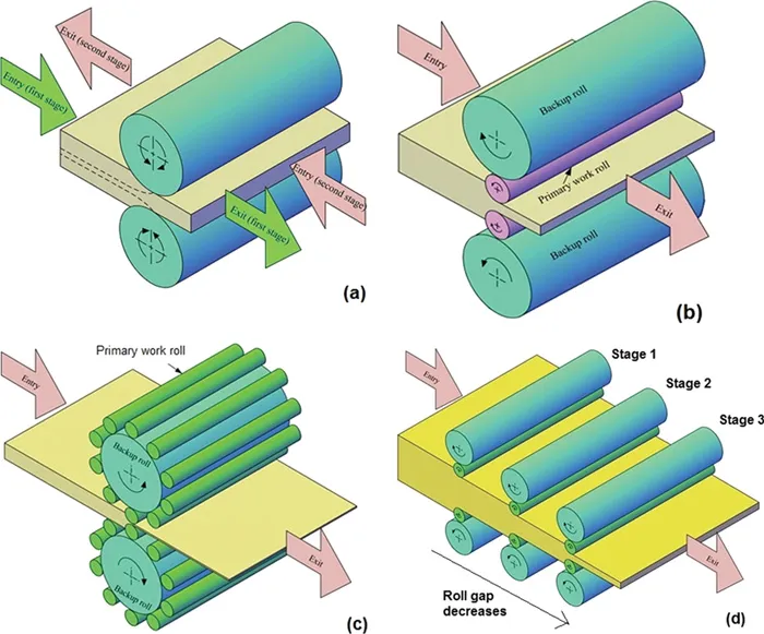
Figure 1.1 Types of roll mill: (a) two-high roll mill, (b) four-high roll mill, (c) planetary roll mill, and (d) roll mill with multiple stands.
In a four-high roll mill, the actual sheet rolling is accomplished by the primary work roll, while large backup rolls support the primary roll (Figure 1.1b). This helps in large thickness reductions without excessive deflection of the primary work roll. Further heavy thickness reductions are possible in special roll mills like planetary mills without roller deflection (Figure 1.1c). Generally, rolling is accomplished in multiple stages called rolling stands (Figure 1.1d). In each stage, predefined and allowable thickness reduction will be aimed. Thickness reductions more than an allowable limit in each stage creates defects in rolled sheets.
In a forging process, a billet is converted into a shaped product with the help of rigid tools. This can be classified into open-die forging and closed-die (or impression die) forging. In open-die forging, the billet has no restriction to flow during deformation and takes the shape until fracture occurs. A simple example for this is simple upsetting operation, through which bulged head of a bolt can be made (Figure 1.2a). On the other hand, in closed-die forging (or impression die forging), a prescribed shape present in the die is given to the billet, making the final product or a semi-finished product (Figure 1.2b). Swaging and radial forging are used to reduce the area of cross-section of the rod or tube either at the end or at any intermediate distance. A metallic container, like a water bottle (Figure 1.3), can be made with the processes. In swaging, a rotating die hammers the workpiece with mechanized up–down movement to deliver a particular shape, while in radial forging, the dies do not rotate, but the rod/tube does (Figure 1.3).
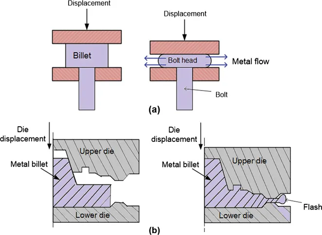
Figure 1.2 Forging processes: (a) open-die forging and (b) closed (impression) die forging.
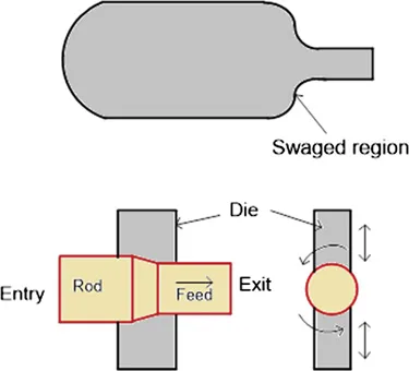
Figure 1.3 Swaging and radial forging.
In extrusion, a billet undergoes plastic deformation through dies by reducing its area of cross-section. The punch compresses the billet against the die (or die opening) through which the metal gets extruded taking the shape and size of the die opening. The cylindrical rods and tubes, as well as the shaped rods and tubes, are generally made through extrusion process. This is classified into forward extrusion, backward extrusion, and lateral extrusion (Figure 1.4), depending on the direction of metal flow with respect to punch displacement. During forward extrusion, the metal flows in the same direction as that of punch movement. There is a relative movement between billet and the die wall, and friction exists between the billet–die wall and the billet–punch interfaces. In backward extrusion, the metal gets displaced in the opposite direction as that of punch displacement, and there is no relative motion between the billet and die walls. Less friction is prevalent during backward extrusion and hence the load requirement is lower in backward extrusion as compared with forward extrusion. In lateral extrusion, the metal flow direction is at some angle to the ram movement that helps the material to get processed at varied strain severity.
In wire drawing or rod drawing, force is applied on the exit side of the billet for a product to be made, as opposed to extrusion in which the force is applied on the entry side. In other words, the billet or wire is pulled at the die exit, as opposed to pushing in extrusion of rods. Wires (<5 mm diameter) are made in wire drawing. There is no need to support wire on the entry side during wire drawing, while a support is required for a rod during rod drawing. Tube drawing can be conducted either with continuous mandrel or with floating mandrel to support the tube and to control its thickness during deformation (Figure 1.5).
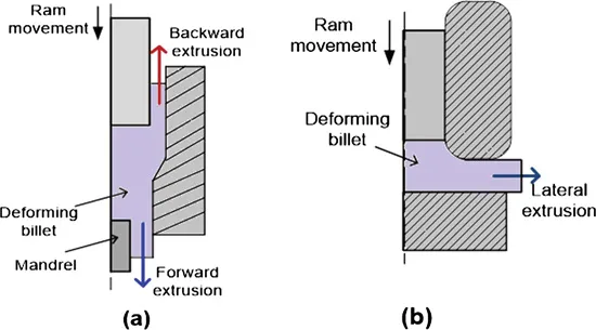
Figure 1.4 Extrusion processes: (a) forward and backward extrusion and (b) lateral extrusion.
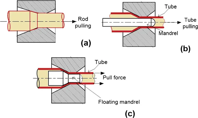
Figure 1.5 Wire, rod, and tube drawing: (a) rod drawing, (b) tube drawing with continuous mandrel, and (c) tube drawing with floating mandrel.
Deep drawing of sheet materials is used to fabricate sheet products by plastically deforming the sheet into the die hole while clamping it with the help of blank holder. Finally, a cup-like component is made without wrinkling and failure. Beverage cans, washbasins, cooking utensils, cylinders, automotive body parts, pressure vessels, etc., are made using deep drawing. The purpose of the blank holder is to minimize wrinkling during this operation. The schematic representation of cup deep drawing operation is shown in Figure 1.6a. The deep drawing involves complex deformation with tension and straightening in the cup wall, tension at the bottom, compression, and friction at the flange region (the sheet part lying on the die surface), bending at the punch and die radius. Generally, cup deep drawing cannot be completed in a single stage and the sheet will be redrawn at multiple stages. The operation is called redrawing. The cup can be redrawn by forward redrawing or reverse redrawing (Figure 1.6b,c).
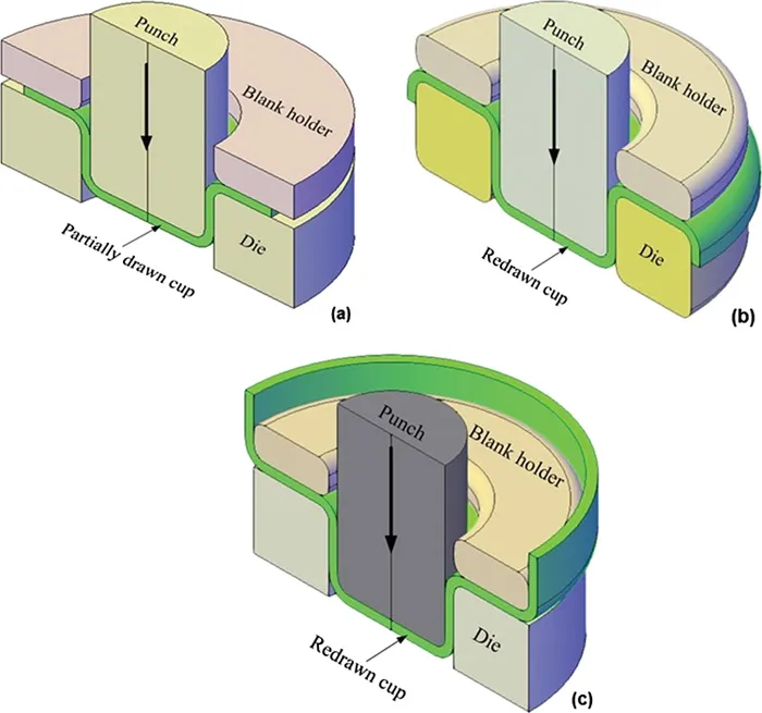
Figure 1.6 Cup deep drawing: (a) single-stage deep drawing, (b) reverse redrawing, and (c) forward redrawing.
In stretch forming (or stretching), a sheet clamped under tension is formed into the die opening with a rigid punch. The sheet is clamped at designated locations with the help of lock beads or drawbeads, and then is wrapped around the punch to give a permanent shape change. Both continuous and discontinuous drawbeads are used for stretching. This operation is primarily used to make automotive door panels, automotive roof, aircraft skin panels, window frames, etc. The stretching, like deep drawing, is accompanied with bending that helps in reducing the springback of the formed part. In bending of sheets, deformation is concentrated in a small curved region, resulting in a nonuniform deformation across the thickness and curvature of the sheet. The bending operations, like V-bending, L-bending, and U-bending, are shown in Figure 1.7. The dies used are different in these operations, resulting in different product shapes, with U-bending resulting in a channel-type component. In the bent region, the sheet outer surface undergoes tension and the inner surface undergoes compression. Springback occurs during bending because of elastic recovery and is compensated by overbending, bottoming the sheet metal, materials processing, etc.
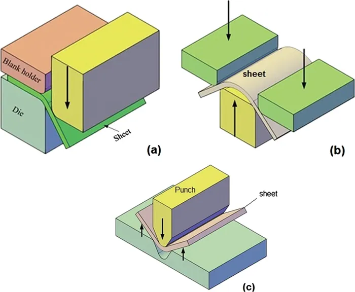
Figure 1.7 Sheet bending operations: (a) L-bending, (b) U-bending, and (c) V-bending.
1.1.2 Joining Processes
Most of the traditional joining processes involve fusion welding processes such as arc welding, gas welding, resistance welding, soldering, brazing, and adhesive bonding. A brief overview about these processes is given here. In arc welding, an electric arc is generated between the electrodes (consumable or nonconsumable), and the base plate. After melting and solidification, a joint is formed (Figure 1.8a). Temperature of the order of 5,000°C is witnessed in the process. The electrodes used in the process can be either consumable or nonconsumable. If they are consumable, the electrode melts (acts as a filler material) and forms the joint, while if they are nonconsumable, the electrode just generates the arc without melting, but gets depleted in length because of vaporization. The inert gases, such as helium and argon, are used as shielding gases, or fluxes are used for the arc shielding purpose. The flux also provides a protective atmosphere for welding, stabilizes the arc, and reduces spattering. The method of providing flux and shielding gas decides the type of arc welding. For example, with consumable electrodes, shielded metal arc welding uses a consumable electrode consisting of a filler rod coated with chemicals that provide flux and shielding. In gas metal arc welding, the consumable wire electrode is fed from a spool, and shielding gas is provided by a separate hose, and both are combined using a nozzle. In flux-cored arc welding, the electrode wire in the form of tube, with flux core, is fed from a spool, while shielding gas is provided separately. In submerged arc welding, a bare electrode wire is provided separately, while flux is fed in the form of flowing granules, such that the arc and electrode tip are submerged. In tungsten inert gas (TIG) arc welding, a nonconsumable electrode (like tungsten) and shielding gas are provided separately. The sustainability issues in welding come in the form of optimized process parameters, selection of electrode material, shielding gas usage and recycling, flux usage and removal, and efficient melting or non-melting of base materials.
In gas welding, the oxyacetylene gas welding is used predominantly. Here a flame generated by the combustion of oxygen and acetylene is used to provide heat required for welding (Figure 1.8b). The filler rod is provided separately if needed. The filler rod is coated with a flux that helps to prevent oxidation, thus creating an efficient weld joint. Instead of acetylene, hydrogen, propylene, propane, and natural gas are also used sometimes. In the case of resistance spot welding, two opposing electrodes are used to generate heat at the contacting surfaces creating spot welds (Figure 1.8c). The electrodes used are copper-based and refractory-b...
Table of contents
- Cover
- Halftitle Page
- Title Page
- Copyright Page
- Contents
- Preface
- Acknowledgments
- Editors
- Contributors
- Chapter 1 Introduction to Sustainable Manufacturing Processes
- Chapter 2 Sustainability in Material Forming
- Chapter 3 Sustainability in Joining
- Chapter 4 Friction and Lubrication in Sustainable Metal Forming
- Chapter 5 Development in Materials for Sustainable Manufacturing
- Chapter 6 Steel: A Sustainable Material of the Future
- Chapter 7 Strategies to Improve the Forming Quality of Sheets
- Chapter 8 Computations and Sustainability in Material Forming
- Chapter 9 Hot Stamping of Ultra-High-Strength Steel Parts
- Chapter 10 Tubular Hydroforming and Hydropiercing
- Chapter 11 Some Recent Developments in Microforming
- Chapter 12 Mechanical Joining Processes
- Chapter 13 Hybrid Joining Processes
- Chapter 14 Green Lubricants and Lubrication
- Chapter 15 LASER-Based Manufacturing as a Green Manufacturing Process
- Chapter 16 Models and Approaches for Sustainable Performance Measurement
- Chapter 17 Sustainable Manufacturing—Getting Future Ready
- Chapter 18 Dissemination of Sustainability and Education
- Chapter 19 Sustainability, Health, and Environment: A Case Study of Waste Management Sector
- Author Index
- Subject Index
Frequently asked questions
Yes, you can cancel anytime from the Subscription tab in your account settings on the Perlego website. Your subscription will stay active until the end of your current billing period. Learn how to cancel your subscription
No, books cannot be downloaded as external files, such as PDFs, for use outside of Perlego. However, you can download books within the Perlego app for offline reading on mobile or tablet. Learn how to download books offline
Perlego offers two plans: Essential and Complete
- Essential is ideal for learners and professionals who enjoy exploring a wide range of subjects. Access the Essential Library with 800,000+ trusted titles and best-sellers across business, personal growth, and the humanities. Includes unlimited reading time and Standard Read Aloud voice.
- Complete: Perfect for advanced learners and researchers needing full, unrestricted access. Unlock 1.4M+ books across hundreds of subjects, including academic and specialized titles. The Complete Plan also includes advanced features like Premium Read Aloud and Research Assistant.
We are an online textbook subscription service, where you can get access to an entire online library for less than the price of a single book per month. With over 1 million books across 990+ topics, we’ve got you covered! Learn about our mission
Look out for the read-aloud symbol on your next book to see if you can listen to it. The read-aloud tool reads text aloud for you, highlighting the text as it is being read. You can pause it, speed it up and slow it down. Learn more about Read Aloud
Yes! You can use the Perlego app on both iOS and Android devices to read anytime, anywhere — even offline. Perfect for commutes or when you’re on the go.
Please note we cannot support devices running on iOS 13 and Android 7 or earlier. Learn more about using the app
Please note we cannot support devices running on iOS 13 and Android 7 or earlier. Learn more about using the app
Yes, you can access Sustainable Material Forming and Joining by R.Ganesh Narayanan, Jay S Gunasekera, R.Ganesh Narayanan,Jay S Gunasekera in PDF and/or ePUB format, as well as other popular books in Technology & Engineering & Industrial Engineering. We have over one million books available in our catalogue for you to explore.