![]()
Part 1
NoC-Based System-Level Design
![]()
1 NoC and System-Level Design
1.1 INTRODUCTION TO SOC DESIGN
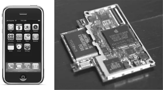
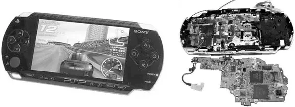
Recently, the term SoC (System on Chip) has replaced VLSI (very-large-scale integration) or ULSI (ultra-large-scale integration) as the key word in information technology (IT). The change of name is nothing but a reflection of the shift of focus from “chip” to “system” in the IT industry. Before the SoC, semiconductor technology and circuits themselves played the central role as a discipline and industry, and engineers needed to master semiconductor circuits and technology to enhance the performance of components in the known target system. However, in the SoC era, the engineer is required to provide a system solution to the target problem with the final end application in mind. These SoCs are widely used in portable and handheld systems such as cell phones and portable game devices, as shown in Figure 1.1 and 1.2.
You may wonder what the system is and how it is different from the chip design in providing a system solution. There are many definitions according to different viewpoints, but in this book system is defined as “a set of components connected together to achieve a goal as a whole for the satisfaction of the user.” It is clear that a system has an end user who wants to use it to do a specific job; it is a little bit different from the component semiconductor chip used as a part of the system. A system usually has an embedded user interface as a form of software and encompasses many components inside, not only the hardware but also the software that constitutes the system. Such a complicated entity can be handled only with computer-aided design tools, automatic synthesis of the physical layouts, and sound software engineering knowledge. In addition, the system functions to achieve a specific goal, as a whole, are usually described in algorithms that should satisfy user requirements in time, conveniently.
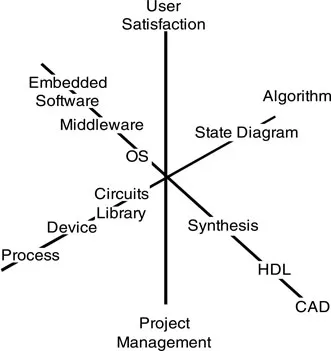
Therefore, the discipline of SoC design is intrinsically complicated and covers a variety of areas, such as marketing, software, computing system, and semiconductor IC design, as described in Figure 1.3. SoC development requires hexagonal expertise in not only technological areas such as IC technology, CAD, software, and algorithm but also in management techniques—complicated team, project, and customer research. In this chapter, we will take a look at different views on SoC design, overall, and its relation to Network on Chip (NoC) in regard to low power consumption.
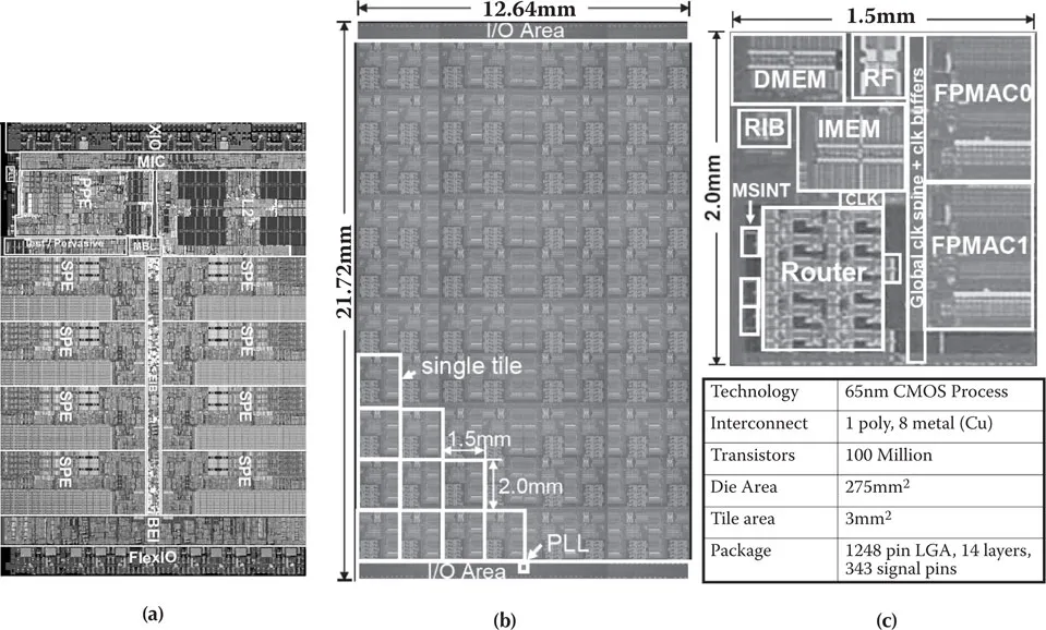
The first concept in SoC was just to copy the system implemented in a PCB onto a silicon chip. By adopting the same bus architectures as those used in the PCB, the processing of embedded applications was implemented on a single chip by assembling dedicated hardwired logics and known general-purpose processors. This concept gave birth to the idea of reuse of the design, as off-the-shelf standardized IC components were soldered on a PCB. The functional circuit blocks can be predesigned and verified for later integration into the SoC as a design component, not a fabricated chip. However, such preverified and reusable designs, called intellectual property (IP), were difficult to assemble because they were developed for performance optimization in house, neglecting the general interface matching. Besides, PCB buses were not appropriate for the on-chip environment. However, on-chip bus performance can be further improved by using specific on-chip characteristics such as increased bit width, low power, higher clock frequency, and tailored interface architectures. The mismatch of interfaces can be solved if IP interfaces are fixed or standardized. Figure 1.4 shows examples of large-scale SoCs, which are fashioned by design reuse. Figure 1.4a shows a chip photomicrograph of the Sony Emotion Engine [1], which has eight high-performance processors integrated on a chip. Intel’s research chip, which has 80 CPUs inside, is shown in Figure 1.4b and the unit CPU, in Figure 1.4c [2].
Figure 1.1 Apple i-Phone and its system board.
Figure 1.2 Sony PSP and its inside boards.
Figure 1.3 Disciplines required for the design of SoC.
Figure 1.4 Chip photomicrograph of (a) Sony Emotion Engine, (b) Intel 80-core Processor, and (c) the detail of a unit processor.
1.1.1 SYSTEM MODEL AND DESIGN FLOW
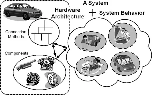
System design is the process of implementing the desired application for the end user by integrating a set of physical components, software, and functions. It cannot be realized straightaway, but as design time proceeds, it gets closer to being manufactured, depending on the given constraints. Because of its complexity, it is more practical and convenient to describe and handle the system in an abstract form, ignoring the detailed physical components and functions during the early design phase. A system can be divided into three conceptual parts: a collection of simpler subsystems, the method for the subsystems to be connected together, and the collective behavioral operations of the entire system. The three parts present an analogy with the automobile, as shown in Figure 1.5. The subsystems such as the engine, tires, and wheels should be assembled by “a specific connection method” to make a car. The connection method is the key to making a unique car model with a specific performance. In addition, the hardware, in total, should provide the system “behaviors” for end-user applications such as speed driving, touring and, baggage transporting.
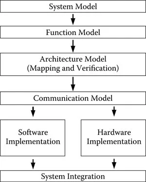
The method for the selection and connection of the subsystems to implement the functions is called the model [3]. Further, it can be divided into three submodels, the system model, the function model, and the architecture model, as shown in Figure 1.6. Only the system’s behaviors are visible to the end user, and its essential characteristics and architectures will be designed based on those behaviors. Usually, models use a particular language such as C or C++ or, of late, a graphical language such as Unified Modeling Language (UML) to describe the system.
First, the system requirements (e.g., what the SoC wants to realize) should be examined. Then, these are refined into system specifications, in which the performances of the system are specified; however, the implementation details are not determined yet. Because the system solution needs to be implemented on an SoC, the software running on the embedded CPU also should be designed concurrently (see Figure 1.6). This is the major difference between the SoC and VLSI designs. Therefore, the design process involves the determining which part of the specification will be implemented in hardware and which, in software.
Figure 1.5 Concept of system, behavior, and architecture.
Figure 1.6 SoC design flow.
Once the concept of the target system is grasped, the set of functions to realize the system specification should be derived and divided into more affordable unit functions. Therefore, the functional specification of a system is determined as a set of functions, which calculate the outputs from the inputs. In this design stage, UML is frequently Once the concept of the target system is grasped, the set of functions to realize the system specification should be derived and divided into more affordable unit functions. Therefore, the functional specification of a system is determined as a set of functions, which calculate the outputs from the inputs. In this design stage, UML is frequently used and will be briefly explained in Subsection 1.1.2. The system model is developed using the system’s behavioral specification, and it is executable in a high-level language and linked to an executable specification of the system’s environment. ...