
- 192 pages
- English
- ePUB (mobile friendly)
- Available on iOS & Android
eBook - ePub
About this book
This book is intended to serve as a source of practical, technicalinformation for those persons in the biotechnology industry. Casestudies and/ or actual industry examples are used to support the textwherever possible. While much of the material contained within thistext is equally applicable to nonbiopharmaceutical processes, theemphasis has been focused directly upon biopharmaceuticalmanufacturing.Section I provides an in-depth analysis of the design concepts thatlead to cleanable equipment. Also covered in the tirst section arecleaning mechanisms and cleaning systems. The first section isparticularly useful to those persons faced with the task of designingsystems that will be cleaned and also provides the biochemicaloockground of the mechanisms associated with the removal of commonbiotechnology soils.Section II focuses on cleaning validation concepts. While thematerial is equally useful for single product cleaning, emphasis isplaced upon multiproduct cleaning validation. Included in Section IIare general validation principles as thex apply to cleaning validation,detailed analxsis of cleaning process validation, sampling techniques,analytical methods and acceptance criteria. The material in this sectionwill be useful to anyone responsible for the development of a cleaningvalidation program.The final section, Section Ill, provides an overview of multiproductbiotechnology manufacturing procedures. Included in this section is ananalysis of tne risk-to-benefit scenarios associated with the various formsof product manufacturing, analysis of changeover programs, ~uipmentconsiderations, and material transfer systems as they are affected bymultiproduct manufacturing strategies.
Tools to learn more effectively

Saving Books

Keyword Search

Annotating Text

Listen to it instead
Information
Topic
MedicineSubtopic
PharmacologySection I
DESIGN CONCEPTS
Section I provides information that can be used to design a sound and effective cleaning program. Included in this section is a thorough review of equipment design principals, cleaning mechanisms and cleaning systems.
The most important factor in any cleaning program is the equipment being cleaned. Chapter 1, “Process Equipment Design Considerations,” provides an analysis of process equipment design principles. Good design of production equipment and associated piping increases the likelihood of successful cleaning. Often an afterthought, a well thought-out design can frequently eliminate costly manual cleaning procedures or reduce cleaning cycle times. The design of processing equipment such that it can be readily cleaned and validated is a demanding process involving the selection of appropriate materials of construction, finishes, and 3–dimensional design. This chapter examines process system design, mechanical design, surface finish and instrumentation concepts. Using specific examples drawn from the biotechnology industry, each aspect of design is examined and demonstrated for applications ranging from bioreactors to chromatography and filling equipment.
The design of a sound, effective cleaning process, whether Clean-in-Place (CIP), Clean-Out-of-Place (COP), or manual requires a basic understanding of the physical and chemical mechanisms of cleaning. Chapter 2, “Cleaning Mechanisms and Strategies,” examines the chemistry and physics of biotechnology soils, soil removal processes, cleaning agents and soil-to-surface interactions. Building upon this foundation, the soil-to-surface and cleaning agent interaction is discussed as it relates to automatic cleaning strategies. Cleaning programs for typical biotechnology process equipment are provided that apply the cleaning mechanisms and processes described earlier in the chapter.
An in-depth analysis of automated cleaning systems used in the biopharmaceutical industry is presented in Chapter 3, “Automatic Cleaning Equipment.” CIP systems continue to evolve as both the cleaning and the biotechnology industries evolve. This chapter focuses on the principles employed in typical CIP systems including portable, re-use, and eductor assisted single use systems. Instrumentation used in currently employed CIP systems is also covered, emphasizing the aspects critical to effective system design.
1
Process Equipment Design Considerations
Typically, the “cleanability” of process systems and equipment is an afterthought when designing biopharmaceutical facilities. Project teams involved in facilities design, as well as architectural and engineering design firms, often specify individual pieces of equipment without considering how the equipment will be cleaned. Vendors of bioreactors, chromatography columns, ultrafiltration skids, and other processing equipment focus on their own areas of expertise. All of these groups assume that equipment cleaning is the responsibility of the clean-in-place (CIP) system vendor. This approach to equipment design is inefficient and may lead to excessive costs due to energy usage, chemical costs, and validation costs. Relying on the CIP system vendor to ensure that equipment can be cleaned is analogous to relying on the vendor of a clean steam system to ensure that process equipment can be sterilized.
A more efficient approach is to design process systems and equipment so that they can easily be cleaned. Proper equipment design for cleanability can yield significant benefits: cleaning time can be reduced, chemical use and energy costs can be minimized, and the amount of manual cleaning and disassembly required can be reduced. More importantly, cleaning validation will be simplified, and facility start-up will be faster. Proper equipment design for cleanability is especially important for start-up, validation, and approval of multiple use facilities.
This chapter explores some of the most important criteria for design of cleanable process systems and equipment.
PROCESS SYSTEM DESIGN
The single most important consideration in the development of a cleanable process system is the integration of appropriate cleaning technology into the overall process system design at the conceptual and schematic stages of design. This integration can be successfully accomplished only after the needs of one’s specific process have been identified and prior to approval of the piping and instrumentation drawings (P&IDs). Understanding the process begins with a process flow analysis, and continues with an analysis of containment requirements and residue properties. Once these elements of the process are understood, one can determine the configuration of both the cleaning and the processing circuits. A major objective at this stage is the development of a process system design in which the cleaning circuits are as simple as possible, the cleaning is easily effected, and the number of circuits is minimized.
Process System Analysis
One of the first steps in designing cleanable processing systems is to conduct a process flow analysis. This analysis consists of the review of process flows, manufacturing methods and procedures, and production schedules. The resulting analysis should include a review of basic unit operations (e.g., media preparation, fermentation, cell processing, filtration) to establish the sequence of steps and any interactions between steps. This information is important to cleaning system design because it is used to determine how the process equipment and its interconnecting piping can be segmented into logical cleaning circuits.
Containment Requirements
One constraint unique to the biopharmaceutical industry is the containment requirements of the process organism and its residues. For instance, if the process organism containment requirements are less stringent (as for GLSP or BL1 organisms), more piping system flow control options are available (such as transfer panels) because of the ability to use “make/break” connections. Conversely, if the process uses an organism with more restrictive containment requirements, the piping system design options may become restricted. For example, waste from a containment restrictive process may have to be inactivated in the processing equipment or sent directly to a biowaste treatment vessel rather than be circulated or sent to drain. These issues can greatly affect the design of the process and its interconnecting piping and cleaning circuit configuration.
Residue Characteristics
The types of in-process residues encountered can also affect cleaning circuit and piping system configurations. Examples include residues that are toxic or that are difficult to keep suspended in cleaning solutions. In these cases, the processing equipment and interconnecting piping in a given cleaning circuit may need to be minimized to prevent deposition on surfaces that do not contact the residue during normal processing operations.
Cleaning and Process Piping Configuration
Once the process flow, containment, and residue characteristics are understood, the processing and cleaning piping configurations should be established. Effective cleaning circuit configuration relies on the process flow analysis described above to determine the sequence and availability of process equipment for cleaning. Once this has been established, the process system can be divided into logical groupings (or circuits) for cleaning based upon equipment and interconnecting piping availability, residue residence times, and similarity of scale and function.
The overall goal of the piping design should be to automatically clean as much of the processing equipment and interconnecting piping as possible while minimizing the total number of cleaning circuits. There are several ways to minimize the number of cleaning circuits, including utilizing process lines as CIP supply/return, combining lines in series in a circuit, and combining lines in parallel in a circuit. A final consideration is the isolation of the dedicated CIP piping from the process piping. This isolation can be accomplished in several ways and it is essential to protect against product contamination from cleaning fluids.
The design of the interconnecting process and cleaning piping as an integral system typically yields far superior cleaning results to other piping configurations. An “integral design” refers to a piping system in which as much process piping as possible is used to supply or return cleaning solutions to or from the processing equipment being cleaned. This approach often minimizes the number of cleaning circuits because of the dual usage of process piping for cleaning supply or return. It also can yield a more cleanable design as the number of connection points between the dedicated cleaning and process piping is minimized.
For example, on a bioreactor, the clean steam header may be used to distribute CIP supply. This approach reduces the valve count by eliminating the CIP header, and the cleaning of steam blocks is improved by eliminating dead legs.
To further reduce the number of cleaning circuits, separate process lines may be linked in series during cleaning. However, care must be taken to assure that the CIP supply pump can maintain minimum flow requirements in the largest diameter lines, despite the flow restrictions of the smallest diameter lines.
To reduce cleaning cycle completion time, various sections of the process equipment may be cleaned in parallel. This may require an engineering analysis to verify that the pressure drops in each parallel leg are similar at the required cleaning flow rates. While the engineering analysis method is generally preferred, a method to verify the actual flow rate in each parallel path may be required, as in instances where residues of high viscosity occur.
A final consideration in the design of process piping is that it should be isolated from dedicated cleaning piping in a fail-safe manner. This approach guarantees the integrity of the process piping system as cleaning solutions are prevented from leaking into product containing lines and equipment. Common approaches include removable spool pieces, transfer panels, and special valving arrangements. A transfer panel is an organized way to handle make-break connections or removable spool pieces. If valves are used for isolation they should be arranged in a double-block-and-bleed configuration. That means that there are two valves in series between the process piping and the dedicated CIP piping (this is the double block), and the space between them is vented to the atmosphere during isolation (this is the bleed). Specialized valves are available that provide this function in a compact arrangement.
Regardless of the isolation approach, the isolation should be verified before each cleaning operation to prevent the possibility of a costly product contamination. The verification may be visual or may use electronic/magnetic sensors to verify the proper status of a spool piece or valve.
Case Study 1.1
A new BL3 cell culture process is to be designed that includes media preparation tanks that supply a seed bioreactor and large bioreactor. Bioreactor harvest utilizes a skid mounted filtration system connected to both the bioreactor and a harvest vessel with flexible connections. The equipment is to be designed such that automated cleaning methods can be used (see Figure 1.1).
Analysis of the process flows indicates that media is supplied to the large bioreactor via a 1 1/2" hard piped connection. The seed bioreactor is hard piped to the large bioreactor with a 3/4" line. The large bioreactor has a fixed vertically mounted agitator, a sight glass, four lop mounted 2" ports. Since the process is for a BL3 organism, containment will be a major concern. This means that there can be no make/break connections prior to decontamination. This presents some interesting design challenges as it is likely that the media prep vessel, the seed fermentor and the large bioreactor will have to be cleaned separately due to the relative timing of each operation. It is likely that the interconnecting piping will contain a combination of double block and bleed valving and make/break connections so that the system can be cleaned in a contained manner without dead-ends at double block and bleed points.
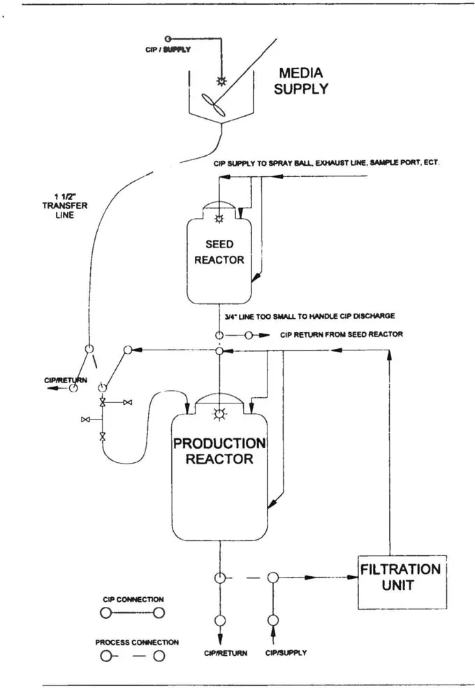
Figure 1.1
Example Case
Example Case
The media prep tank and its transfer piping would likely be configured as a single CIP circuit, with the CIP return point adjacent to the large bioreactor. This return point may be a make/break connection as there are no cells in the media prior to fermentation.
The seed bioreactor and its transfer line to the large bioreactor would also likely comprise a single CIP circuit. The 3/4" discharge line might present problems with regard to CIP return from the vessel and should be enlarged. Typically, CIP requirements dictate changing some process line sizes. If the line size cannot be increased, then nitrogen or air top pressure (5—10 psig) may be added to the vessel during CIP, pushing the CIP return fluid out of the vessel. All of the “feeds” into the seed bioreactor should be cleaned in this single CIP cycle, and these may include exhaust piping and filters, gas and/or steam sparging lines, media and/or additive piping, etc. Each of these, while likely small in diameter, will contribute to the overall flow requirements of the circuit and may require automated sequencing as the operation of all at once may result in more flow than can be handled by the 3/4" discharge line. The CIP return point for this cycle will be adjacent to the large bioreactor and, for containment reasons, will be segregated by double block and bleed valving. A make/break connection may also be added upstream of the double block and bleed valving so that they can be thoroughly cleaned later with the large bioreactor.
The large bioreactor, its transfer line to the filtration unit and the filtration unit would likely comprise a single CIP ci...
Table of contents
- Cover
- Title Page
- Copyright Page
- Table of Contents
- Preface
- About the Authors
- Introduction
- Section I DESIGN CONCEPTS
- Section II VALIDATION CONCEPTS
- Section III MULTIPRODUCT CONCEPTS
- Glossary
- Appendix
- Index
Frequently asked questions
Yes, you can cancel anytime from the Subscription tab in your account settings on the Perlego website. Your subscription will stay active until the end of your current billing period. Learn how to cancel your subscription
No, books cannot be downloaded as external files, such as PDFs, for use outside of Perlego. However, you can download books within the Perlego app for offline reading on mobile or tablet. Learn how to download books offline
Perlego offers two plans: Essential and Complete
- Essential is ideal for learners and professionals who enjoy exploring a wide range of subjects. Access the Essential Library with 800,000+ trusted titles and best-sellers across business, personal growth, and the humanities. Includes unlimited reading time and Standard Read Aloud voice.
- Complete: Perfect for advanced learners and researchers needing full, unrestricted access. Unlock 1.4M+ books across hundreds of subjects, including academic and specialized titles. The Complete Plan also includes advanced features like Premium Read Aloud and Research Assistant.
We are an online textbook subscription service, where you can get access to an entire online library for less than the price of a single book per month. With over 1 million books across 990+ topics, we’ve got you covered! Learn about our mission
Look out for the read-aloud symbol on your next book to see if you can listen to it. The read-aloud tool reads text aloud for you, highlighting the text as it is being read. You can pause it, speed it up and slow it down. Learn more about Read Aloud
Yes! You can use the Perlego app on both iOS and Android devices to read anytime, anywhere — even offline. Perfect for commutes or when you’re on the go.
Please note we cannot support devices running on iOS 13 and Android 7 or earlier. Learn more about using the app
Please note we cannot support devices running on iOS 13 and Android 7 or earlier. Learn more about using the app
Yes, you can access Cleaning and Cleaning Validation by Jon Voss in PDF and/or ePUB format, as well as other popular books in Medicine & Pharmacology. We have over one million books available in our catalogue for you to explore.