- 400 pages
- English
- ePUB (mobile friendly)
- Available on iOS & Android
eBook - ePub
Masonry Bridges, Viaducts and Aqueducts
About this book
For 2,000 years the most durable spanning structures have been built of masonry, and the surviving bridges of the Roman Empire have challenged master masons, architects and engineers to emulate and surpass them. Down the centuries, bridge-builders have been commissioned by monarchs, bishops, councils of state, cities, private individuals and, more recently, waterway and railway companies. The studies collected in this volume focus chiefly on the bridges, viaducts and aqueducts themselves and the actions of the designers and builders, but also encompass the political, economic and social contexts and outcomes of their creation. Famous bridges in Britain, Italy, France, Iran and the USA are all featured. Narratives of conception, design and construction predominate, but there are also papers on construction techniques, on the analysis of documentary sources, and on the continuing search by modern engineers for satisfactory scientific description of the strength and stability of arch bridges.
Trusted by 375,005 students
Access to over 1.5 million titles for a fair monthly price.
Study more efficiently using our study tools.
Information
1
Testing times for arches
B. Harvey
ARCHED BRIDGES are naturally elegant structures. Preservation orders protect many arched bridges, and very few defile their surroundings. Of the hundred thousand bridges that connect roads in Britain, about seventy thousand are arches. Thousands more arches carry railway lines and canals. Some of the biggest arches—Thomas Telford’s Over Bridge at Gloucester and the railway viaducts at Ballochmyle and Ribblehead, for example—inspire awe. The smallest may span only 2 or 3 metres across a stream, but even they have considerable value.
It might cost a hundred thousand pounds to replace a modest bridge on a minor road, so we can value the arches that carry Britain’s roads at £7000 million or more. Some bridges are more valuable than others. Ribblehead Viaduct would cost about £4 million to replace, according to a recent estimate. Other bridges are important because they carry a disproportionate amount of traffic, or because they are tourist attractions in their own right. Peter Colechurch’s Old London Bridge, built around 1176, earned so much money from tolls before it was replaced in 1831 that the invested capital has paid for all four bridges in the City—London, Tower, Southwark and Blackfriars—since then. The bridge across the River Tay in Aberfeldy, designed by William Adam and built for General George Wade in 1733, draws crowds all summer and brings income to the local community.
If a bridge closes, or new regulations restrict the weight of the vehicles using it, local businesses have to live with the commercial strain. On the other hand, people living near a bridge often have a vested interest in weight restrictions, which they might disguise as concern for the bridge. The engineers, employed by the council to care for old bridges and design new ones, must consider politics and conservation as well as structural soundness when assessing whether a bridge is safe to carry traffic.
Money for maintaining arches is hard to come by, for the simple reason that they rarely fall down. People often regard them as truly fixed assets. On the whole engineers subscribe to this popular view, though recent changes in the weights of vehicles have encouraged them to think more deeply. Until quite a short time ago, the weight of the vehicles passing over a bridge was negligible compared with the weight of the bridge itself. Now, however, vehicles with five axles weighing 38 tonnes gross can go anywhere on Britain’s roads. Some of these vehicles are greatly overloaded, yet they use bridges that were built to carry horses.
Every bridge is regularly inspected: its strength is reassessed at least every six years. Engineers base that assessment on a mixture of science and judgment. The complexity of the problem limits the value of the science, however, as no two arches are alike. The shape may be semicircular, segmental, elliptical or even pointed. The arch might be of dressed stone voussoirs (wedge-shaped blocks), bricks or rough stone. The road may be high on a bank of earth over the arch, or it may rest directly on the back of the ring. The road may be level, sloping or humped. The space between the arch and the road—the spandrel—may be filled with earth, stone or concrete. Some spandrels are hollow.
The science of arches developed slowly . The Romans seem to have believed that force followed the ring of the arch. (The ring comprises the blocks that line the underside of the arch.) The Romans thought, as a result, that semicircular arches exerted only vertical forces on their supports. In fact, the concrete that filled the spandrels in Roman arches carried the neglected horizontal forces.
Throughout the Renaissance, engineers and architects struggled to understand what happened to the forces inside an arch. In 1675, Robert Hooke hit upon the idea that an arch was simply the inverse of a loaded chain hanging across the same span (Box 1). The line of the chain represents the line of thrust—a line joining the points of greatest stress in each block of the arch’s ring (Box 2).
Hooke was an inspired thinker and an experimentalist, but he lived in an age dominated by Isaac Newton and theory. When Hooke hinted at his ideas on arches, the Secretary of the Royal Society wanted to give Newton or Christopher Wren the credit. Hooke finally presented his theory, which he had proved by experiment, as a Latin anagram at the end of a paper describing helioscopes. A translation of the solution to the anagram reads: “As hangs a flexible cable, so, inverted, stand the touching pieces of an arch.” Hooke could claim precedence, but the dispute dragged on and, although many scientists knew of the solution, he never formally published it.
Unlike many architects and engineers in the 17th century, Thomas Young clearly understood all the implications when he wrote his article “Bridge” for the Encyclopaedia Britannica in 1817. He explained that a very thin arch will stand up if it is exactly the right shape for the loads imposed on it. Deepening the blocks which make up the ring of the arch allows the arch to withstand the complex pattern of loads produced as a vehicle crosses the bridge. The ring must be wide enough to accommodate all the different lines of thrust that result.
1: Hooke’s experimental approach to the arch
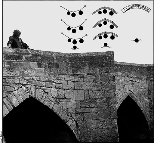
HOOKE used two types of model to show how arches work—flexible cables, and rods joined together with pins. Many different shapes of cable can support the same loads in the same positions. In each case, as in the three examples on the far left, the tension in the cable is different. If you displace the cable, it will swing back to its initial position. This form of stability is similar to that of a ball sitting in a dish: it will always roll back to the centre if you move it.
If you use jointed rods to form a shape similar to that of a cable supporting different weights, and invert it, it will stand. Unlike the cable, the structure is unstable (although friction in the joints of Hooke’s models allowed these structures to stand up). Once displaced, the pinned rods will collapse, just as a ball will roll off an upturned dish.
The line of the chain or the cable in Hooke’s models represents the line of thrust. In a real arch built with deep voussoirs (wedge-shaped blocks), many lines of thrust will fit, as the diagram on the immediate left shows. The arch is thus overstable: it will take a large force to displace it. Once you remove that force, the arch will snap back into position. The structure’s stability is now similar to that of a ball sitting in the bottom of a conical cup.
An arch with a much thinner ring allows only one line of thrust to fit within the arch and support the loads. The arch is still stable—but only just.
2: How an arched bridge responds to stress
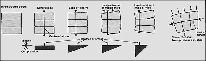
Load, affects the distribution of stress. Cracks form between the blocks once the centre of stress moves outside the blocks’ middle third
STONE deforms when it is under stress. The diagrams show three blocks of stone, stacked together without mortar. Stress (pressure) develops between the stones to resist any applied load. The centre of stress—the point of greatest stress—is always directly in line with the load. As the stress increases, it compresses the stone. There can be no tensile stress because the stones would simply move apart.
If the load moves away from the centre of the blocks, the stress increases at the edge towards which the load has moved, allowing the centre of stress to stay in line with the load. When the load is one-third of the way across the blocks, the stress falls to zero at the edge farthest from the load. The maximum stress is then double what it was when the load was at the centre of the blocks.
Moving the load further in the same direction causes cracks to open, the distribution of stress is still triangular, and the centre of stress is still at the point at the base of the triangle. Where the stress is zero, the blocks are not squashed, so the sections of the blocks between the cracks are the same shape as they were originally.
In a real arch, tapered blocks, called voussoirs, often make up its ring. The diagram above on the far right shows the forces imposed on three voussoirs in the ring of an arch.
The forces in the ring represent the effect of stress on the sloping faces of the stones. Other forces, applied on the extrados (the longer curved edge of the ring), cause the force to turn through an angle as it passes through the blocks. In this case, engineers call the line through the centres of stress the line of thrust.
The diagram below shows the line of thrust through a real arch at the point of collapse. Wherever the line passes outside the middle third of the voussoirs, cracks should develop on the unloaded face. Mechanism analysis (Box 3) assumes that one wide crack will open at each of four points. In practice, many narrow cracks will often appear, although they may be difficult to see.
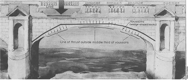
The typical line of thrust in a real bridge at the point of collapse. The loads on the bridge include the arch’s own weight, pressure from the material filling the spandrels and the load from the vehicle’s wheels. Loads distributed over a wide area cause the line of thrust to turn smoothly. Concentrated loads cause it to turn sharply. If you increase the load any further, the line of thrust will move outside the arch’s ring, and the bridge will fall down.
In France, in 1730, Pierre Couplet studied the way in which an arch collapses when it is overloaded. He found that models folded up with very little deformation of the arch between the “folds”. It is much easier to calculate the load at which collapse will occur (Box 3) than it is to compute the line of thrust generated by a lesser load:—a “safe working load”, for example—but engineers did not appreciate the value of this approach until recently. They were concerned with how things stood up, not with how they fell down.
Throughout the 19th century, many practising engineers developed methods for computing the line of thrust of an arch. Most of them realised that it was sufficient to find any line of thrust which would support the required loads. However, the engineers still pursued a method that would provide them with a single solution to the problem.
In 1879, Alberto Castigliano, an engineer in Turin, Italy, produced such a method. He calculated how the arch would deform under a load. He could then work out the pattern of stress through the ring of an arch and thus the line of thrust. The calculation was complex and tedious, but it did lead to a single solution. Unfortunately, his analysis considered only the arch and assumed that the supporting abutments remained rigid. In fact, small movements of the supports produce large changes in the distribution of stress within an arch. As most foundations move, engineers now view Castigliano’s results with caution.
Towards the end of the 19th century, engineers in France and Austria resorted to testing large-scale models to help them to design arches with longer spans than those that already existed. This method of proving designs is good, provided that the scale of the model is large enough, but it is very expensive. Some of the Austrian models had a span of 23 metres and a rise of only 4⋅6 metres. These arches were so strong that only explosives would induce them to collapse. In France, engineers built a model with a span of 36 metres and a rise of only 2⋅1 metres. That arch proved equally resilient. The French never built the intended bridge, however, which would have had a span of 120 metres. The bridge with the longest span ever constructed, some 90 metres, stands in Plauen, in the German Democratic Republic.
The advent of cheap steel and concrete meant that the popularity of arched bridges waned early this century. However, interest in arches—particularly in how to maintain them—began to revive in the 1930s. Although most vehicles were still relatively light, military appliances were rapidly increasing in weight and the army needed to be certain that a bridge would carry them. The problem of how to assess existing bridges presented itself for the first time. Alfred Pippard and his research assistant, Letitia Chitty, began a new study of models in 1936. They cooperated with Norman Davey of the Building Research Station, near Watford, on some full-scale tests. Their efforts resulted in the Military Engineering Experimental Establishment’s (MEXE) method of assessment, which, modified by the Ministry of Transport, is still in use today.
3: Mechanism analysis—or how bridges collapse
IF YOU overload a model arch, it collapses by folding up. Individual, voussoirs—the wedge-shaped blocks that’ form the ring of the arch—deform negligibly because the stresses on them are so low (Box 2). But cracks form at four points, alternately on the inner and outer curves of the arch’s nng—the intrados and extrados. We can regard the points of contact between the sections as hinges.
If we slowly increase the load until the fourth crack just forms, the bridge reaches a state of unstable equilibrium, almost collapsing. The line of thrust passes through the root of each hinge. Each section of the arch A, B and C is just in balance, rotating neither to the left nor to the right.
The turning effect of the forces acting on each section must then be in balance, so we can write an equation describing that balance for each section, or for combinations of sections. Thus at crack 3, the weight of section C and the horizontal force at crack 4 are trying to turn section C clock wise, while the vertical, force at crack 4 is trying to turn this section anticlockwise. At hinge 2, the weights of. sections B and. C, plus the horizontal force, all act one way, resisted by the vertical force. At hinge the weight of section A and the load are also involved.
We can, of course, measure the dimensions of the arch and calculate the weights of each section of arch, so we can form three simultaneous equations with three unknowns. Solving these equations gives us approximate values for the horizontal and vertical forces and for the load which will just cause the arch to collapse. The values are only approximate because we have had to estimate the position of the hinges.
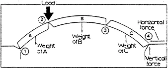
We can represent the approximate values for the horizontal and vertical forces as two sides of a triangle whose lengths correspond to the ratio between the two values. The slope of the triangle’s hypotenuse gives us the slope of the line of thrust at hinge 4. We can plot this line back through the arch: if our calculations are wrongs the line of thrust will pass, outside the arch. In this case, we choose, new positions for the hinges and repeat the process until the line of thrust stays within the ring. We then use the new values for the horizontal and vertical forces to give us a more accurate value for the load that will cause the bridge to collapse.
Real arches also contain filling to bring the road up to the required level. The weight of the filling acts downwards like the weight of the arch itself, but the filling can also push sideways on the arch. The amount of sideways force is difficult to assess, but neglecting this effect nearly always leads to a low result for the calculated load at which collapse will occur.
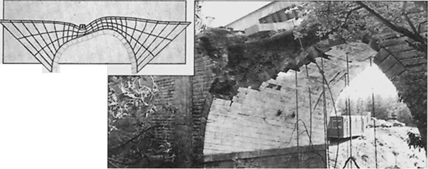
This semicircular arch at Bridgehouse, near Bargower. failed fits masonry crushed) at a higher load man computerised analysis (above) predicted. Its filling of stone made it stronger
Pippard used Castigliano’s method to calculate the value of a load at a central point which should cause cracking. This load would take the line of thrust just outside the middle third of the depth of the ring of the arch (Box 2). Yet when Davey tested the bridges, he could see no cracks even at much higher loads. Indeed, there were still no cracks at the load that Pippard calculated should take the line of thrust outside the middle half ...
Table of contents
- Cover Page
- Title Page
- Copyright Page
- Contents
- Acknowledgements
- General Editor’s Preface
- Introduction
- 1 Testing times for arches
- 2 The Roman bridge-builder: some aspects of his work
- 3 The Pont du Gard and the aqueduct of Nîmes
- 4 Vitruvius and the elevated aqueducts
- 5 Resistance to technological innovation: the history of the pile driver through the 18th century
- 6 Rebuilding the bridge at Albi, 1408–1410
- 7 Le Pont du Rialto: un chantier public à Venise à la fin du XVIe siècle
- 8 The Pul-i Khwājū in Isfahan: a combination of bridge, dam and water art
- 9 Berwick-on-Tweed Bridge
- 10 Hollow spandrels in arch bridges: a historical study
- 11 Pont-y-ty-pridd: a critical examination of its history
- 12 William Edwards’s bridge at Pontypridd
- 13 The foundations of Hexham Bridge
- 14 Pulteney Bridge
- 15 Two masonry bridges. II. Telford’s bridge at Over
- 16 Arch bridges
- 17 Valley crossings on the Old Croton Aqueduct
- 18 The Canton Viaduct
- 19 The fall of Barentin Viaduct, 10 January 1846
- 20 The safety of masonry arches
- Index
Frequently asked questions
Yes, you can cancel anytime from the Subscription tab in your account settings on the Perlego website. Your subscription will stay active until the end of your current billing period. Learn how to cancel your subscription
No, books cannot be downloaded as external files, such as PDFs, for use outside of Perlego. However, you can download books within the Perlego app for offline reading on mobile or tablet. Learn how to download books offline
Perlego offers two plans: Essential and Complete
- Essential is ideal for learners and professionals who enjoy exploring a wide range of subjects. Access the Essential Library with 800,000+ trusted titles and best-sellers across business, personal growth, and the humanities. Includes unlimited reading time and Standard Read Aloud voice.
- Complete: Perfect for advanced learners and researchers needing full, unrestricted access. Unlock 1.5M+ books across hundreds of subjects, including academic and specialized titles. The Complete Plan also includes advanced features like Premium Read Aloud and Research Assistant.
We are an online textbook subscription service, where you can get access to an entire online library for less than the price of a single book per month. With over 1.5 million books across 990+ topics, we’ve got you covered! Learn about our mission
Look out for the read-aloud symbol on your next book to see if you can listen to it. The read-aloud tool reads text aloud for you, highlighting the text as it is being read. You can pause it, speed it up and slow it down. Learn more about Read Aloud
Yes! You can use the Perlego app on both iOS and Android devices to read anytime, anywhere — even offline. Perfect for commutes or when you’re on the go.
Please note we cannot support devices running on iOS 13 and Android 7 or earlier. Learn more about using the app
Please note we cannot support devices running on iOS 13 and Android 7 or earlier. Learn more about using the app
Yes, you can access Masonry Bridges, Viaducts and Aqueducts by Ted Ruddock in PDF and/or ePUB format, as well as other popular books in Technology & Engineering & Architecture Methods & Materials. We have over 1.5 million books available in our catalogue for you to explore.