![]()
Chapter 1
Introduction
Anchors are a critical component of floating and compliant structures used in coastal and ocean engineering applications. This book presents the application of geomechanics for understanding and predicting anchor performance. Geomechanics provides the analytical framework for characterizing the interaction of the anchor with the soil in which it is embedded. It is central to two aspects of anchor behavior: embedment of the anchor into the seabed to a sufficient depth to ensure that it can fulfill its intended function and the resistance of the anchor to pullout under applied working loads. Other engineering specialties contribute to anchor design, each of which could occupy a volume of its own; these include fatigue and corrosion, mooring line system design in the water column, the dynamics of floating structures, the mechanical hardware for anchor installation, instrumentation for monitoring anchor performance, and the vessels and logistics for transporting and installing anchors. These topics are largely outside of the scope of this book, aside from occasional mention of their impact on geotechnical behavior. Thus, anchor geomechanics is one of a number of specialties contributing to the design of mooring systems, but one of central importance.
The focus of the coverage in this book is largely directed toward anchors for offshore energy infrastructure, historically dominated by oil–gas exploration and production, but with an emerging focus on floating renewable energy systems. Many of the basic principles guiding the analysis of anchors for offshore energy infrastructure apply equally to anchors for ships and naval vessels, and findings from naval research laboratories has often been applied to anchors used for floating energy facilities. However, design constraints can tend to push the development of anchors for these applications in diverging directions. A main driver guiding the design of anchors for offshore energy development is maximizing the pullout load capacity of anchors. Pullout capacity is also a consideration for ship anchors, but other factors constrain their design, such as rapid installation and extraction, and the necessity of avoiding excessively deep embedment to reduce the potential for snagging cables and pipelines. A glance at an anchor load capacity chart will show commonly used anchors for shipping to have an order of magnitude lower capacity than the high-capacity anchors favored by the energy industry. The apparent “inefficiency” of commonly used anchors for ships is driven by constraints that do not normally occur in energy applications.
In regard to organization of this book, this introductory chapter provides an overview of the common types of floating and compliant structures secured by anchors, different categories of anchors, the physical mechanisms by which anchors resist pullout, how the nature of loading affects anchor performance, and criteria for evaluating anchor performance. This introductory chapter contains few quantitative formulations and is intended to provide the reader with an intuitive grasp of these topics; rigorous development of theoretical formulations and analytical methods is saved for later chapters. The remainder of this book comprises three major segments:
•Chapters 2 through 5 cover basic principles relevant to all anchor types, in successive order these include soil mechanics, relevant analytical methods from geomechanics, fundamental solutions that have been applied to all categories of anchors, and anchor line mechanics.
•Chapters 6 through 8 cover cylindrical anchors, with Chapter 6 covering caisson and pile installation, Chapter 7 ultimate load capacity, and Chapter 8 elastic response and soil–pile interaction.
•The final major segment is plate anchors, with Chapter 9 covering drag embedded anchors (DEAs) and Chapter 10 covering various types of directly embedded plate anchors.
1.1Floating and compliant structures
As development progresses to greater water depths, the cost of fixed structures increases exponentially, driving the use of floating or compliant structures secured to the seabed by anchors. In deep water, it is also more difficult and expensive to hold the natural periods well below the dominant sea state period. The more common of these structures are described below.
1.1.1Semisubmersible
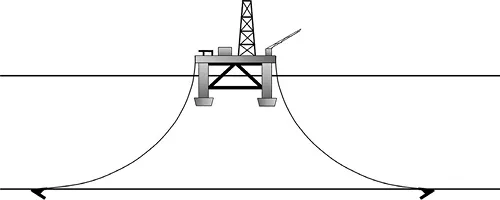
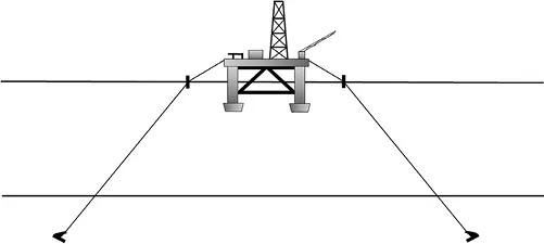
A semisubmersible (Randall, 1997) is a floating structure comprising large vertical columns supported by large pontoons at the bottom. It floats high in the water while being towed to the site. The pontoons are then flooded to partially submerge the structure, the majority of which is below water. Only the columns are exposed to environmental loading, which contributes to the stability of the structure. A semisubmersible can be moored to the seabed using catenary or taut systems, as illustrated in Figures 1.1 and 1.2. Catenary moorings apply essentially horizontal loads on anchors, while taut moorings are inclined up to approximately 30–35° from horizontal. The mooring lines can comprise chain or wire rope, the latter are lighter but more prone to damage and corrosion. In deep waters, catenary moorings require excessively large offsets, resulting in an increased likelihood of encroaching upon adjacent tracts, crossing mooring lines from adjacent facilities, or crossing undersea pipelines. Hence, for these situations, taut mooring systems provide a more attractive method of mooring floating platforms. In deep water, the weight of the mooring line itself becomes a significant design consideration, a problem which has been addressed through the introduction of lightweight synthetic mooring lines (Vryhof, 2015).
Figure 1.1Semisubmersible with catenary mooring system.
Figure 1.2Semisubmersible with taut mooring system.
1.1.2Tension leg platform
A tension leg platform (TLP) consists of a semisubmersible vessel moored by vertical tendons connected to the seafloor, as illustrated in Figure 1.3. The excess buoyancy of the structure—typically on the order of 15%–25% of the platform displacement—maintains the tendons in tension even under the worst storm loading conditions. Conoco constructed the first TLP in the British sector of the North Sea in the early 1980s in approximately 150 m of water. This structure was selected for relatively shallow water as a test of the concept prior to use in deep waters. Since then, several deep water TLPs (>450 m) have been installed. The foundations for TLPs usually consist of large diameter pipe piles that provide resistance to uplift through skin friction, although suction caissons (Section 1.2.1) can be used. Loading on the foundation consists of a tensile mooring force and cyclic loading owing to wave loading on the superstructure. Loading is predominantly vertical with lateral forces estimated at less than 10% of vertical forces. A critical loading condition most likely occurs when a change in mean sea level owing to a storm surge occurs in conjunction with large wave loading. TLPs can provide a feasible platform alternative to water depths from approximately 450 to at least ...