- 266 pages
- English
- ePUB (mobile friendly)
- Available on iOS & Android
eBook - ePub
Control Engineering
About this book
Since its inception, the Tutorial Guides in Electronic Engineering series has met with great success among both instructors and students. Designed for first- and second-year undergraduate courses, each text provides a concise list of objectives at the beginning of every chapter, key definitions and formulas highlighted in margin notes, and references to other texts in the series.With emphasis on the fundamental ideas and applications of modelling and design, Control Engineering imparts a thorough understanding of the principles of feedback control. Simple but detailed design examples used throughout the book illustrate how various classical feedback control techniques can be employed for single-input, single-output systems. Noting the interdisciplinary nature of control engineering, the author makes the text equally relevant to students whose interests lie outside of electronics by concentrating on general systems characteristics rather than on specific implementations.The author assumes students are familiar with complex numbers, phasors, and elementary calculus, and while a knowledge of simple linear differential equations would be useful, this treatment has few other mathematical requirements. With its clear explanations, copious illustrations, well-chosen examples, and end-of-chapter exercises, Control Engineering forms an outstanding first-course textbook.
Tools to learn more effectively

Saving Books

Keyword Search

Annotating Text

Listen to it instead
Information
Systems, objectives and strategies 1
Objectives
- To introduce the concept of control in an engineering context, and to indicate the wide variety of control tasks in a large engineering system.
- To describe the three common control strategies – open loop, feedforward, and feedback (or closed-loop control).
Introduction
The word ‘control’ is used in many different contexts. We talk of quality control, financial control, command and control, production control, and so on – terms which cover an enormous range of activities. Yet all these types of control, if they are to be successful, have certain features in common. One is that they all presuppose the existence of a system whose behaviour we wish to influence, and the freedom to take actions which will force it to behave in some desirable way. For example, for the manager of a large chemical plant the system of interest may be the entire plant, as illustrated in Fig. 1.1. The inputs to the system, which we assume the manager can influence, are the various flows of energy and raw materials into the plant; the outputs are not only the finished products but also the waste, environmental effects, and so on. Note that there are also disturbance inputs, which the manager cannot control, such as market fluctuations, changes in the environment, etc., and these will also affect the plant outputs. For another engineer in the same plant, however, the system of interest might be one particular reaction vessel and specifically, the design of a control system to maintain the reactants at a constant temperature by adjusting the flow of steam to a heater, as represented in Fig. 1.2. From a control point of view there is a single input (steam flow rate) and a single output (reactor temperature); in addition, there will again be disturbances caused by various outside factors such as unwanted fluctuations in the steam supply or changes in the ambient temperature.
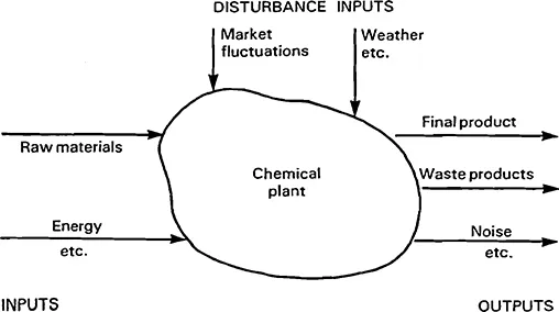
Fig. 1.1 A chemical plant considered as a single system.
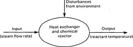
Fig. 1.2 A reactor subsystem of the chemical plant.
In general, a system can be defined loosely as the set of interconnected elements which are of interest for some specific purpose.
No control system can be designed without a clear specification of control objectives. For a chemical plant as a whole, the ultimate control objective might be to produce a final product meeting quality specifications, while minimizing costs. For the temperature control system the objective might be to remain within a certain temperature range under specified operating conditions. In each case, however, there will be limitations or constraints on what can be achieved; not only limits to the physical capabilities of the equipment being used, but also, for example, economic, legal, and safety constraints.
Control engineering can perhaps be summed up as the design and implementation of automatic control systems to achieve specified objectives under given constraints. For a complex system, the overall objectives and constraints will need to be translated into performance specifications for the various subsystems -ultimately into control system specifications for low-level subsystems, such as individual chemical reactors in the chemical plant example.
Control engineering as a discipline is characterized by a common approach to a great variety of control tasks, and by a set of mathematical tools which have proved to be generally applicable. Computers are used widely to implement control schemes, and an increasing knowledge of information technology and software engineering is therefore being demanded of control engineers. Nevertheless, the fundamental requirement is still a thorough understanding of the dynamics of individual control systems. This book will concentrate on those strategies, models and techniques vital to this understanding.
Control strategies
This text will deal with single-input, single-output systems only. Such systems can be represented by a block diagram such as Fig. 1.3, which shows a single-input, single-output process to be controlled.
In the introduction to this chapter the terms input and output were used very generally to signify any flow of information, energy or material into or out of a system. From now on, however, the terms will be used more precisely. In Fig. 1.3, for example, u(t), the ‘input’ to the process, represents the variable which is adjusted in order to bring about the control action: it is often known as the manipulated variable. Similarly y(t), the ‘output’ of the process, is the variable which the engineer wishes to control in order to fulfil the desired objectives: not surprisingly, it is referred to as the controlled variable. Hence in the temperature control system mentioned above the ‘input’ (manipulated variable) was the rate of flow of steam and the ‘output’ (controlled variable) was the temperature – even though to a chemical engineer the various reactants and products might be perceived as the system inputs and outputs! To a control engineer, inputs and outputs are defined so as to represent a signal flow through the control system, a concept which will become clearer in subsequent chapters.
The term ‘process’ is used generally to mean any system to be controlled. The term ‘plant’ is often also used with exactly the same meaning.
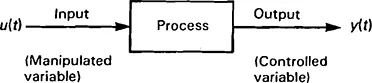
Fig. 1.3 A single-input, single-output process.
Returning to Fig. 1.3, then, we can express the goal of all controllers – whether automatic systems or human operators – as attempting to achieve a desired output behaviour y(t) by applying an appropriate control action u(t) to the process. Automatic controllers or control systems do this by using information about the process and the particular operating conditions to determine an appropriate u(t) for a given situation, as represented by Fig. 1.4. Such information might include externally supplied data about operating conditions – such as the desired and current values of y(t), the rate at which y(t) is changing, and so on – but also ‘built-in’ information which takes into account how the process is likely to behave in response to a particular control action.
The latter, ‘built-in’ information is derived from a model of the process which can be used to predict the variation of y(t) for a given applied u(t). Models of process behaviour are vital if a control system is to be designed which will automatically generate an appropriate control action, and the sort of models commonly used by control engineers will be described in some detail in Chapter 3. First, however, let us examine a number of general approaches or control strategies which can be adopted. All require the process to be modelled, but thf general characteristics of each strategy can be described without making any particular assumptions about the type of model employed.
Modem automatic control systems are based on the use of digital computers or microprocessors to generate the required control action. Digital and computer control is discussed in detail in Chapters 9, 10, 11 and 12.
The first strategy, known as open-loop control, is illustrated in Fig. 1.5. The controller can be thought of as using an ‘inverse’ model of the process, together with externally-supplied information about the desired output, to determine controlaction. A simple example should make this clearer. Figure 1.6 shows an open-loop motor speed control system. Suppose that we have a model relating the motor armature voltage to the resulting motor speed. Using such a speed/voltage relationship, we can attempt to design an open-loop controller such that the armature voltage generated in response to a given desired speed (as defined by the position of a control knob, for example) is just what is required, in theory, to produce that particular motor speed. If the motor speed/voltage relationship is modelled by a constant – say Grad s–1 v–1 – then the effect of the controller and power amplifier combined must be to produce 1/G volts for each rad s–1 of demanded speed. In this simple case the open-loop controller attempts to implement the exact inverse model, 1/G.

Fig. 1.4 The general control problem.
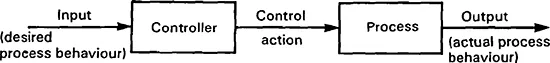
Fig. 1.5 The open-loop strategy.
The precise form of the model used will depend on many factors, including the objectives of the control system. The modelling process will be discussed in detail in Chapter 3.
There are various drawbacks to this type of control strategy, however. If the load on the motor changes, the speed will alter even if the demanded speed, and hence the armature voltage, is held constant. Furthermore, the characteristics of the motor may vary with time – for example, the speed obtained for a given voltage when the motor is cold may be very different from that when the lubricating oil in the bearings has reached its normal operating temperature. Open-loop control cannot compensate for either disturbances to the system (such as a varying load) or changes in plant parameters (such as varying friction in the bearings).
One way of compensating for disturbances is to measure them and make corresponding changes to the control action, as illustrated in general terms in Fig. 1. 7. Here one input to the controller represents the desired behaviour of the process in some way. The control action taken by the controller is determined not only by using a model of how the process behaves, but also by taking into account the measured disturbances. In the case of the temperature control system of Fig. 1.2, for example, disturbances to the steam supply system might conceivably be measured and the value used to open or close a sup...
Table of contents
- Cover
- Half Title
- Title Page
- Copyright Page
- Table of Contents
- Preface to the second edition
- Preface
- Acknowledgements
- 1 Systems, objectives and strategies
- 2 General characteristics of feedback
- 3 Modelling dynamic systems
- 4 The frequency response approach to control system design
- 5 The s-plane and transient response
- 6 The root-locus technique
- 7 Steady-state performance
- 8 Controllers and compensators
- 9 Digital control I. Discrete system models
- 10 Digital control II. Sampled-data systems
- 11 Digital control III. Introduction to digital design
- 12 Computers and control
- Appendix 1 Polar plots
- Appendix 2 The Routh–Hurwitz criterion
- Appendix 3 Frequency response of discrete linear systems
- Answers to numerical problems
- Further reading
- Index
Frequently asked questions
Yes, you can cancel anytime from the Subscription tab in your account settings on the Perlego website. Your subscription will stay active until the end of your current billing period. Learn how to cancel your subscription
No, books cannot be downloaded as external files, such as PDFs, for use outside of Perlego. However, you can download books within the Perlego app for offline reading on mobile or tablet. Learn how to download books offline
Perlego offers two plans: Essential and Complete
- Essential is ideal for learners and professionals who enjoy exploring a wide range of subjects. Access the Essential Library with 800,000+ trusted titles and best-sellers across business, personal growth, and the humanities. Includes unlimited reading time and Standard Read Aloud voice.
- Complete: Perfect for advanced learners and researchers needing full, unrestricted access. Unlock 1.4M+ books across hundreds of subjects, including academic and specialized titles. The Complete Plan also includes advanced features like Premium Read Aloud and Research Assistant.
We are an online textbook subscription service, where you can get access to an entire online library for less than the price of a single book per month. With over 1 million books across 990+ topics, we’ve got you covered! Learn about our mission
Look out for the read-aloud symbol on your next book to see if you can listen to it. The read-aloud tool reads text aloud for you, highlighting the text as it is being read. You can pause it, speed it up and slow it down. Learn more about Read Aloud
Yes! You can use the Perlego app on both iOS and Android devices to read anytime, anywhere — even offline. Perfect for commutes or when you’re on the go.
Please note we cannot support devices running on iOS 13 and Android 7 or earlier. Learn more about using the app
Please note we cannot support devices running on iOS 13 and Android 7 or earlier. Learn more about using the app
Yes, you can access Control Engineering by Chris Bissell in PDF and/or ePUB format, as well as other popular books in Technology & Engineering & Civil Engineering. We have over one million books available in our catalogue for you to explore.