- 408 pages
- English
- ePUB (mobile friendly)
- Available on iOS & Android
eBook - ePub
Electrical Insulation in Power Systems
About this book
Covers the design, operations, diagnostics and testing of electrical insulation in high-voltage power networks. The book presents the fundamental properties of dielectrics essential for the optimum design of power systems. It provides a survey of advanced digital and electro-optic techniques used in both the field and research.
Tools to learn more effectively

Saving Books

Keyword Search

Annotating Text

Listen to it instead
Information
1
Introduction to Electrical Insulation in Power Systems
1.1 INTRODUCTION
The economic development and social welfare of any modern society depends upon the availability of a cheap and reliable supply of electrical energy. Extensive networks of electrical power installations have been built in industrialized countries and are being constructed in developing countries at an ever-increasing rate. The major function of such power systems is to generate, transport and distribute electrical energy over large geographical areas in an economical manner while ensuring a high degree of reliability and quality of supply.
The transmission of large amounts of electrical power over long distances is best accomplished by using high voltage (HV), extra high voltage (EHV) or ultra high voltage (UHV) power lines (see Table 1.1 for voltage classification). Thus, high voltage equipment is the backbone of modern power systems. Besides generation, transmission and distribution of electrical energy, high voltages are also extensively used for many industrial, scientific and engineering applications such as:
1. Electrostatic precipitators for the removal of dust from flue gases
2. Atomization of liquids, paint spraying and pesticide spraying
3. Ozone generation for water and sewage treatment
4. X-ray generators and particle accelerators
5. High-power lasers and ion beams
6. Plasma sources for semiconductor manufacture
7. Superconducting magnet coils
Table 1.1 Voltage Classifications (V = Rms, Line to Line Voltage)
Voltage class | Voltage range |
Low voltage (LV) | V ≤ 1kV |
Medium high voltage (MHV) | 1 kV < V ≤ 70 kV |
High voltage (HV) | 110 kV ≤ V ≤ 230 kV |
Extra high voltage (EHV) | 275 kV ≤ V ≤ 800 kV |
Ultra high voltage (UHV) | 1000 kV ≤ V |
In all such applications, the insulation of the high voltage conductor is of primary importance. For proper design and safe and reliable operation of the insulation system, knowledge of the physical and chemical phenomena which determine the dielectric properties of the insulating material is very important. In addition, the basic processes which lead to degradation and failure of such materials and appropriate diagnostic techniques are of prime importance since any such failure can cause temporary or permanent damage to the system, thereby influencing its reliability and cost. Considering the high cost and comparatively long life span (20–40 years) of high voltage equipment, every effort should be made to select the most appropriate materials as well as the design, installation and operational parameters for such apparatus. This book attempts to provide an overview of different aspects of electrical insulation as practiced mainly in high voltage power systems.
This chapter outlines some basic definitions and fundamental concepts which are essential for proper understanding of the electrical insulation behavior. It further provides a brief overview of general categories of insulating materials, a short description of their applications and some desirable properties of various classes of dielectric materials. Subsequent chapters provide the detailed properties, applications, failure modes and diagnostic techniques used for evaluating and testing different insulating materials.
1.2 PROPERTIES OF DIELECTRICS
There are several properties of a dielectric which are of practical importance for an engineer. The most important of these properties are briefly defined here.
1.2.1 DC Conductivity
DC conductivity, σ, is defined as σ = J/E where J is current density (in A/m2) resulting from the application of a direct electric stress E (in V/m). It is related to the bulk resistivity ρ of the dielectric by σ = 1/ρ and is calculated from measured values of the insulation resistance. Alternatively, if ρ and geometry are known, insulation resistance can be calculated. Insulation resistance is used as an indication of conduction behavior of insulating materials in many practical applications, such as in hi-pot testing. For most insulating materials, σ depends upon the material purity, its temperature T and electric stress E. It generally increases as the ionic impurities in the insulation system increase. Similarly σ also tends to increase with T and E in most cases following a relationship of the type
(1.1) |
where k is the Boltzman constant, A is a constant, and σ(T) is the value of σ at temperature T. In addition, due to polarization effects, σ also depends upon time of application of the stress. It influences the power losses in a dielectric and controls the electric stress distribution under direct voltage applications.
1.2.2 Dielectric Permittivity
Dielectric permittivity, relative permittivity or dielectric constant, εr, of an insulating material is defined as εr = C/Co, where C is the capacitance between two parallel plates having the space between them filled with the insulating material under discussion, and Co is the capacitance for the same parallel plates when these are separated by vacuum. Generally εr is not a fixed parameter but depends upon temperature, frequency and molecular structure of the insulating material.
1.2.3 Complex Permittivity, Loss Angle and Dissipation Factor
In order to determine the response of dielectrics to alternating voltages, it is traditional to model the dielectric by a parallel RC network. Such a network along with its phasor diagram is shown in Figure 1.1. Here R represents the lossy part of the dielectric taking account of losses resulting from electronic and ionic conductivity, dipole orientation and space charge polarization, etc., and C is the capacitance in the presence of the dielectric as defined earlier. If an AC voltage, v = √2 V sin ωt, is applied then the capacitive component of current is IC = jωCV while the resistive component of current is IR = −jI tan δ. Since loss angle δ is usually very small, IC ≈ I and IR = −jIC tan δ. Hence, total current I = IR + IC can be expressed as:
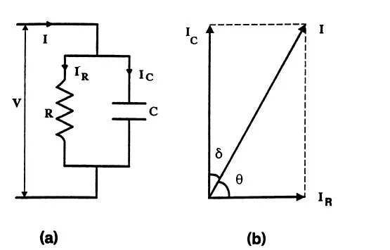
Figure 1.1 (a) Parallel equivalent circuit of a dielectric material and (b) corresponding phasor diagram.
(1.2) |
where ε* = complex relative permittivity having a real part...
Table of contents
- Cover
- Half Title
- Title Page
- Copyright Page
- Table of Contents
- Series Introduction
- Preface
- 1 Introduction to Electrical Insulation in Power Systems
- 2 Gas Dielectrics
- 3 Air Insulation
- 4 SF6 Insulation
- 5 Liquid Dielectrics
- 6 Solid Dielectrics
- 7 Vacuum Dielectrics
- 8 Composite Dielectrics
- 9 High Voltage Cables
- 10 Generation and Measurement of Testing Voltages
- 11 New Measurement and Diagnostic Technologies
- 12 Insulation Testing
- Index
Frequently asked questions
Yes, you can cancel anytime from the Subscription tab in your account settings on the Perlego website. Your subscription will stay active until the end of your current billing period. Learn how to cancel your subscription
No, books cannot be downloaded as external files, such as PDFs, for use outside of Perlego. However, you can download books within the Perlego app for offline reading on mobile or tablet. Learn how to download books offline
Perlego offers two plans: Essential and Complete
- Essential is ideal for learners and professionals who enjoy exploring a wide range of subjects. Access the Essential Library with 800,000+ trusted titles and best-sellers across business, personal growth, and the humanities. Includes unlimited reading time and Standard Read Aloud voice.
- Complete: Perfect for advanced learners and researchers needing full, unrestricted access. Unlock 1.4M+ books across hundreds of subjects, including academic and specialized titles. The Complete Plan also includes advanced features like Premium Read Aloud and Research Assistant.
We are an online textbook subscription service, where you can get access to an entire online library for less than the price of a single book per month. With over 1 million books across 990+ topics, we’ve got you covered! Learn about our mission
Look out for the read-aloud symbol on your next book to see if you can listen to it. The read-aloud tool reads text aloud for you, highlighting the text as it is being read. You can pause it, speed it up and slow it down. Learn more about Read Aloud
Yes! You can use the Perlego app on both iOS and Android devices to read anytime, anywhere — even offline. Perfect for commutes or when you’re on the go.
Please note we cannot support devices running on iOS 13 and Android 7 or earlier. Learn more about using the app
Please note we cannot support devices running on iOS 13 and Android 7 or earlier. Learn more about using the app
Yes, you can access Electrical Insulation in Power Systems by N.H. Malik,A. A. Al-Arainy,M.I. Qureshi in PDF and/or ePUB format, as well as other popular books in Technology & Engineering & Electrical Engineering & Telecommunications. We have over one million books available in our catalogue for you to explore.