1.1 Evolution of Power Electronics
In the history of electrical technology spanning over the past four decades, a few developments have had a large impact upon the general area of power electronics (PE). These are the development and evolution of thyristors, microprocessors, microcontrollers, and so on. During the past few decades, we have seen the impact of PE devices, consisting of thyristors, gate turn-off thyristors (GTOs), power diodes, power transistors, power insulated gate field-effect transistors (IGFETs), power insulated gate bipolar transistors (IGBTs), metal–oxide–semiconductor field-effect transistors (MOSFETs), and so on in all aspects of modern motion control and power utilities [1]. The application of PE devices covers the low-power ranges such as in fractional horse power drives for robots as well as the high-power ranges involving Bay Area Rapid Transit (BART) trains of the United States or in Train á Grande Vitesse (TGV) trains of France. Today, complex control and decision strategies are implemented by PE devices with the help of microprocessors and microcontrollers to extract high performance and operational flexibility. In modern applications, useful features can be extracted even from a simple converter—inverter circuit, when operated as an uninterruptible power supply (UPS) or in high-voltage direct current (HVDC), where solid-state electronics are used in conjunction with PE devices [2,3].
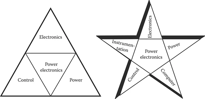
Serious attention has been focused to evolve analytical techniques for predicting and explaining the performances of PE systems [4–6]. Many different techniques of varying degrees of complexities have been proposed to model a PE system. With the advancement in all disciplines during the past few decades, power electronics is now a major common factor in studies in control applications, electronics, and power utilities. In addition, the fields of instrumentation and computers are much involved and dependent on PE [7,8]. Hence, as shown in Figure 1.1, a star pattern has now emerged from a triangle pattern [7].
With the advancement of conventional silicon controlled rectifier (SCR), its GTO variety [9–11] was also manufactured in the 1960s. Its additional feature, that a negative pulse at the gate terminal turns the device off, has proven to be advantageous because it dispenses with the commutation circuitry of the conventional SCR when operated in a DC system. However, till the late 1970s, the power-handling capabilities of the GTOs were not much to credit their widespread application in the industry. However, during the last quarter of a century, technologists have been able to produce high-current GTOs suitable for critical applications involving high power.
Figure 1.1 The changing pattern of PEs with regard to application areas.
Today, we have many types of PE devices satisfying the conflicting demands of various industries. The range of application of these devices is so wide as to make it unlikely that some new products will dominate all the existing ones. Certainly, no contender has yet met all the following specifications—and none possibly ever will, because some of the features are conflicting. These are:
Zero leakage when “off”
Zero impedance when “on”
Zero switching time
Zero switching losses, with no radiofrequency interference
Very sensitive for ease of drive, but immune to spurious triggering
Low cost
Indefinite life: rugged
Convenient packaging: isolated
1.2 Analysis of Power Electronic Circuits
The first mathematical analysis of the two-pulse power converter was carried out by Steinmetz in 1905. However, Dallenbach, who worked under Albert Einstein, was the first to propose the theoretical foundation of multipulse power converters. The theory and analysis of power converter circuits were enriched between 1930 and 1960 by the works of Muller-Lubeck, Marte and Winogard, Denontvignier, Schilling, Uhtmann, Kaganow, Wasserrals, and Rissik [12].
In 1940, Goodhue [13] presented an analysis technique using a rectifying mathematical operator. In his work, he applied his “rectifier calculus” to various rectifier circuits supplied with unbalanced sinusoidal/nonsinusoidal power line voltages. He represented the output voltage wave of a rectifier as a product of two voltage waveforms, one of which was a square wave.
With the exponential growth of the utility of PE systems, it became necessary to analyze and model such a system truthfully with the help of different available mathematical tools. However, each of the different analytical approaches has its own unique advantages as well as disadvantages.
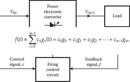
A simple block diagram of a general PE converter is shown in Figure 1.2. The sole objective of the circuit in Figure 1.2 is to convert efficiently the input voltage or a set of voltages VIN, having a particular waveform, to the output voltage or a set of voltages VOUT, having a waveform different from VIN. Normally, VIN is a DC and single-phase or polyphase AC voltage vector. The output of the converter VOUT may be a DC voltage of a different average value and a single-phase or polyphase AC voltage of a magnitude and frequency different from the input voltage.
The conversion in the PE converter is achieved by a set of semiconductor switches—usually thyristors, GTOs, or transistors—triggered in a specific sequence depending on the desired nature of the output voltage. Proper filters may be connected between the input and the output. The triggering or the firing sequence is controlled by the control signal c. But it may so happen that the nature of the switches and the connected load influence the conduction interval, and hence the operation becomes load dependent. This situation is indicated by the feedback signal f in Figure 1.2.
Figure 1.2 Block diagram of a general PE converter.
Due to the complexities mentioned above, the exact analysis of a PE system is seldom feasible, and the exact determination of all significant circuit variables as a function of time is difficult. Thus, the currently available analysis techniques usually look for approximate solutions that are obtained from a simplified linear or nonlinear representation of the system. These techniques are briefly stated in the following.
1.2.1 Fourier Series Technique
This is the oldest method employing orthogonal functions, namely, sine and cosine, which is useful in analyzing physical problems in various fields. In analyzing PE circuits, it is mostly used for phase control techniques [14].
If the load of the switching circuit is considered linear and the voltages applied to the load by the converter are known, the principle of superposition holds and Fourier series may be employed to determine the output variables successfully [15]. For each harmonic, the response is determined by solving the circuit for the respective harmonic equivalent load circuit. These individual responses are then summed to get the approximate output waveform.
However, it should be apparent that the analysis technique is really tedious and has to deal with many harmonic terms even in the case of a simple switching pattern of a PE converter. Most of the times, simplifications are made in the analysis, but this implies loss in accuracy.
1.2.2 Laplace Transform Method
This is one of the most popular as well as versatile methods for solving the problems of PE circuit analysis [16,17]. However, even in the straightforward application of the Laplace transform in most of the practical cases, the mathematical manipulations become quite involved.
In the application of the Laplace transform technique to chopper circuits, the output voltage of the PE controller, VOUT, is represented as segments of a step function. When applied to phase-controlled circuits, VOUT consists of segments of sine waveforms. The basic approach is to express VOUT as a series, in which each term is the product of a sine wave and a switching function consisting of segments of a unit step function. Thus, each term represents a complete period or a quasi-period of the converter output voltage. Once the output voltage is determined, its Laplace transform is obtained by using the well-known formulas.
With VOUT at our disposal, the output load current IL can be expressed in terms of VOUT, the load parameters, thyristor extinction angle, and so on in the transformed Laplace (s) domain. Then, applying the inverse Laplace transform yields an explicit function for the load current as an infinite series.
While the advantage of the method is its exactness, its disadvantages lie in the facts that the mathematics become too involved for determining the transforms and inverse transforms in the Laplace domain, even for simple circuits. In addition, the analysis has to be repeated if one is interested in finding out the output variables for the same load circuit but with different types of controller output voltages VOUT.
1.2.3 Existence Function Technique
Existence functions formally and quantitatively describe the switching pattern of any PE converter. With existence functions, it is possible to obtain not only accurate mathematical formulations of the dependent quantities but also graphical constructions of dependent quantities and internal converter waveforms.
The existence function for a single switch, first introduced in the literature by Gyugyi and Pelly [18], assumes the unit value whenever the switch is closed, and it is zero whenever the switch is open. Within a specified time, the same switch may be closed or opened a number of times, having a variable repetition rate as well as “on”-time duration. If the switch has a fixed “on”-time and a fixed “off”-time duration, the switching pattern may be represented by the simplest unmodulated existence function. The more complex variety, which has different pulse durations and various interspersed zero times, is called a modulated existence function [19].
With the help of existence functions, even very complex switching patterns or switching matrices can be represented. The control variables of the converter system such as duty cycle, repetitio...