![]()
PART 1
Instrumentation and technology
1 The cardiac imaging and monitoring systems
Steven Kelly and Jeffrey Lui
2 Non-invasive physiological monitoring
Mark Butlin, Isabella Tan, Edward Barin and Alberto P. Avolio
3 Determination of oxygen status in human blood
Marcus Juul
4 Coagulation and the coagulation cascade
John Edward Boland and David E. Connor
5 Thrombosis, heparin and laboratory monitoring of heparin therapy
Steven Faddy
6 Laboratory coagulation assays
Bruce Toben and David E. Connor
![]()
1
The cardiac imaging and monitoring systems
STEVEN KELLY AND JEFFREY LUI
Introduction: History
Current technology
Specifications and instrumentation
Where does it all begin?
What is image quality?
‘The bit under the table’
What is the ’1.1.’?
What ever happened to cine film?
Physiological and haemodynamic monitoring
Haemodynamic pressure measurement
Current trends
Workflow enhancements
Radiation dose management
Clinically driven outcomes
Summary
Acknowledgement
Further reading
INTRODUCTION: HISTORY
In November 1895 Wilhelm Conrad Roentgen, a physicist at the University of Wurtzburg in Germany, saw a weak, flickering greenish light on a piece of cardboard coated with a fluorescent chemical preparation while experimenting with a cathode ray tube. Roentgen later verified that the cathode ray tube was the source of invisible rays with an unexpected power of penetration.
A month later the first image of human anatomy, the hand of Roentgen’s wife, was obtained using an exposure time of 30 minutes. He reportedly told his wife, ‘I am doing something that will cause people to say, “Roentgen has gone mad.”’ Whether this quote can be attributed to Roentgen or not, the statement well describes the ensuing furor that ‘he expected’ following the presentation of his paper ‘A New Type of Rays.’
Today, over 120 years later, the ability to see into the living body without need for surgical invasion is perhaps the most historically significant advancement in medical diagnostics, having far-reaching implications for medical therapy, specifically in cardiovascular disease.
In 1929 Werner Forssmann introduced a catheter into his own right atrium via the antecubital vein, with the intent to develop a method of rapid delivery for medications. This event, as reported, involved a nurse tricked into assisting in the procedure and a stroll to the Radiology Department to image the advancement of the ureteric catheter under fluoroscopy to the right atrium. That year, the first X-ray tube featuring a rotating anode disc was released.
Over the next 30 years, cardiac catheterisation developed from a method by which cardiac physiology could be studied experimentally, to an established clinical investigational technique used in the diagnosis of congenital and valvular heart disease. In 1959 cardiac catheterisation became the preferred method for investigation of coronary artery disease.
Advances in radiological and cardiac imaging techniques over the same period included development of the mechanical cassette changer, the serial cut film changer, the image intensifier (1952) and acceptance of 35 mm cine film to capture rapid sequence X-ray images. These developments formed a technical framework on which early imaging systems in the cardiac laboratory were based. In the 1960s television provided an interactive means of obtaining clinical information from an X-ray source.
Cardiologists of the early 1970s, in collaboration with various imaging companies, helped to develop the first dedicated cardiac stand using 35 mm cine film as the recording medium. The first dedicated cardiac stands of this period were based on a parallelogram or U-arm using conventional X-ray generators and featured the image intensifier above the patient.
In 1976 the Optimus Modular 200 X-ray generator and Polydiagnost C (parallelogram based) gantry were introduced. The combination of this generator and gantry formed the backbone in many of the cardiac centres worldwide for the next 20 years. This generator, with its tetrode switching of high-tension voltages, was the first to incorporate the ‘measuring shot’ technique, negating the need to pre-determine the exposure parameters of voltage, current and time.
Advances in cardiac surgery during the 1970s led to coronary artery bypass surgery becoming a viable clinical option for patients suffering coronary artery disease. During this period, significant technological refinements in both surgery and cardiac catheterisation techniques promoted a need for an increased diagnostic yield from cardiac imaging, resulting in the first digital cardiac imaging systems in late 1985.
The enormous demand placed on imaging equipment by routine diagnostic procedures, and more so by prolonged interventional procedures, saw further technical advances in imaging equipment. In 1989, again an advancement specifically tailored to the needs of cardiac imaging, saw the development of the Maximus Rotalix Ceramic (MRC) X-ray tube featuring a continuously rotating anode with liquid metal spiral grove bearing technology. This X-ray tube provided a mechanism by which the enormous heat loadings produced by cardiac procedures could be effectively dissipated, and just as importantly, provided a significant reduction in radiation dose.
Since the initial use of 35 mm cine film as a recording medium, several alternatives have been used, all essentially for cost saving purposes and all in an analogue format of lesser quality than images obtained digitally. In early 1995 this problem was overcome by digital systems using compact disc technology as an archive medium.
CURRENT TECHNOLOGY
The modern cardiac catheterisation laboratory is no longer an X-ray imaging system based on or modified from angiography equipment used in Radiology and demands the highest quality in equipment design and performance. Today’s cardiac laboratory consists of:
1. X-ray generator capable of pulsed fluoroscopy at rates equal to standard acquisition rates of 12.5/15 frames per second (fps) and allowing digital acquisition at rates up to 25/30 fps. An achievable current of 1000 milliamperes (mA) at 100 kilovolts (kV) is essential.
2. X-ray tube incorporating a continuously rotating anode and using liquid metal lubricated spiral groove bearing technology and an oil heat exchanger.
3. High-definition digital dynamic Flat Detector with configurations being either a 12-inch (20 × 20 cm) detector size or a 20-inch (30 × 40 cm) detector size.
4. A large-format, configurable monitor capable of multiple inputs.
5. Digital storage device.
6. Archive device ± review station(s).
7. Networking capabilities for multi-laboratory/multi-centre archive and review.
8. Haemodynamic monitoring system.
Specifications and instrumentation
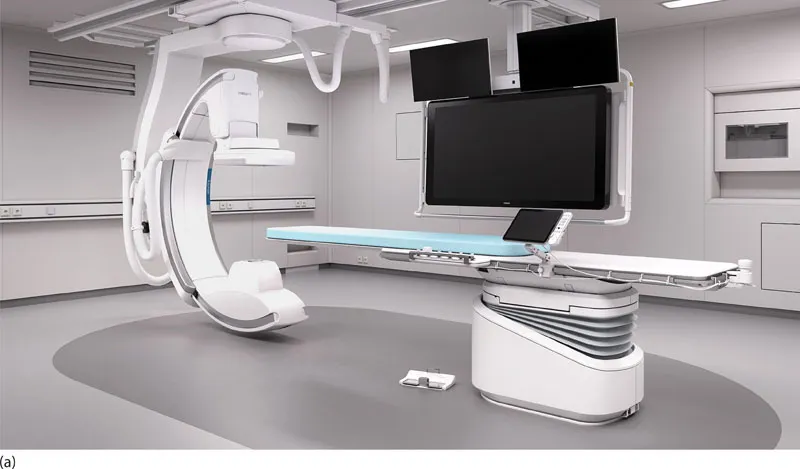
A typical cardiac catheterisation laboratory is shown in Figure 1.1a.
WHERE DOES IT ALL BEGIN?
X-rays are produced within an X-ray tube when electrons from the cathode filament bombard and interact with a rotating disc of metal, the anode. The anode and cathode are mounted a short distance apart. A high voltage is applied between the anode (positive terminal) and the source of electrons, the cathode filament (negative terminal). A high voltage is required to accelerate electrons from the cathode filament and is obtained from a transformer that converts mains voltages (415 V) to the voltages required for diagnostic imaging, 40–130 kilovolts (kV). This transformer and other components form the basis of the X-ray generator. Bombardment of electrons on the heavy metal of the anode results in the generation of X-rays. The anode contains a high proportion of a heavy metal such as molybdenum or tungsten, as heavy metals maximise generation of X-ray energy.
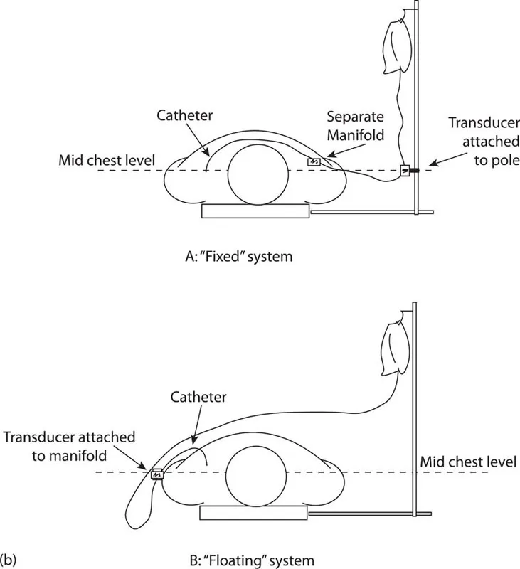
Figure 1.1 (a) Example of a typical ceiling-mounted cardiac catheterisation system. (b) Difference between a transducer system attached to a pole at mid-chest level (‘Fixed’) and one attached to a moveable manifold (‘Floating’). ([a] Courtesy of Philips Healthcare Australia & New Zealand.)
X-ray generators used in cardiac imaging are microprocessor-controlled and contain medium- to high-frequency converters. The kilowatt (kW) is the unit used to describe the power output of X-ray generators. For cardiac imaging up to 100 kW of power is required.
WHAT IS IMAGE QUALITY?
The clinical information obtained in cardiac imaging is a function of spatial resolution and the dynamic contrast range displayed. Image contrast is affected by high voltage. A high kV results in increased penetration and consequently in reduced image contrast. Due to the inherent properties of the iodine-based contrast medium used in cardiac imaging, subtle differences in image contrast are most evident when images are acquired at approximately 70 kV. The high-frequency generators used in cardiac imaging require high output power to allow acquisition of images to occur around this value.
Because cardiac structures move during acquisition, requiring a short generator switching time (‘exposure time’) is required, this value being fixed at approximately 8 milliseconds (ms). To then be able to acquire images without motion artefact and at voltages best suited to iodine based contrast (70 kV), the X-ray generator must operate at currents of at least 500–600 mA, and typically at values up to 1000 mA. This is required to maximise contrast resolution.
The high voltage supply from the X-ray tube accelerates electrons from the cathode. If this voltage varies over time, the X-ray output will change during an exposure, thus influencing image quality. Modern X-ray generators are therefore designed to have very low variation in the higher voltages. The control unit of a generator controls tube current and exposure time, controls anode rotation and has other additional functions.
Much development in recent times has been focused on minimising radiation dosage to the patient, clinician and staff, while still maintaining a medical diagnostic level of image quality to cater for diagnostic and interventional purposes. Today’s technologies better manage the diagnostic and interventional environment with the core consideration of dose management driving recent developments.
‘THE BIT UNDER THE TABLE’
The X-ray tube is contained within a metal housing lined on the inside with lead shielding. The tube housing provides the mechanical connection between the X-ray tube and the rest of the X-ray system and is filled with circulating oil to conduct heat away from the X-ray tube. X-rays are emitted through an opening in the metal housing. The tube is provided with a window made of a very light material such as beryllium or thin glass to permit unrestricted outflow of X-rays in the chosen direction.
A collimator (a mechanism to attenuate, or focus, or restrict a beam of energy into a narrow field or column) is mounted on the X-ray tube housing. The collimator limits the X-ray beam to the minimum area needed for the diagnostic procedure. This protects the patient and operator from unnecessary radiation and improves image quality by reducing the amount of scattered radiation. In some systems an iris diaphragm located within the collimator produces a circular field of irradiation focused to the digital detector. The collimator also contains two pairs of lead shutters that can be adjusted to limit the beam area through a rectangular field. A single or double semi-transparent wedge-shaped filter(s) is incorporated within the collimator to overcome attenuation differences between different anatomical areas.
The rotat...