- 568 pages
- English
- ePUB (mobile friendly)
- Available on iOS & Android
eBook - ePub
Interferogram Analysis For Optical Testing
About this book
In this day of digitalization, you can work within the technology of optics without having to fully understand the science behind it. However, for those who wish to master the science, rather than merely be its servant, it's essential to learn the nuances, such as those involved with studying fringe patterns produced by optical testing interferometers.
When Interferogram Analysis for Optical Testing originally came to print, it filled the need for an authoritative reference on this aspect of fringe analysis. That it was also exceptionally current and highly accessible made its arrival even more relevant. Of course, any book on something as cutting edge as interferogram analysis, no matter how insightful, isn't going to stay relevant forever.
The second edition of Interferogram Analysis for Optical Testing is designed to meet the needs of all those involved or wanting to become involved in this area of advanced optical engineering. For those new to the science, it provides the necessary fundamentals, including basic computational methods for studying fringe patterns. For those with deeper experience, it fills in the gaps and adds the information necessary to complete and update one's education.
Written by the most experienced researchers in optical testing, this text discusses classical and innovative fringe analysis, principles of Fourier theory, digital image filtering, phase detection algorithms, and aspheric wavelength testing. It also explains how to assess wavefront deformation by calculating slope and local average curvature.
Tools to learn more effectively

Saving Books

Keyword Search

Annotating Text

Listen to it instead
Information
1
Review and Comparison of the Main Interferometric Systems
1.1 TWO-WAVE INTERFEROMETERS AND CONFIGURATIONS USED IN OPTICAL TESTING
Two-wave interferometers produce an interferogram by superimposing two wavefronts, one of which is typically a flat reference wavefront and the other a distorted wavefront whose shape is to be measured. The literature (e.g., Malacara, 1992; Creath, 1987) provides many descriptions of interferometers; here, we will just describe some of the more important aspects.
An interferometer can measure small wavefront deformations with a high accuracy, of the order of a fraction of the wavelength. The accuracy in a given interferometer depends on many factors, such as the optical quality of the components, the measuring methods, the light source properties, and disturbing external factors, such as atmospheric turbulence and mechanical vibrations. It has been shown by Kafri (1989), however, that the accuracy of any interferometer is limited. He proved that, if everything else is perfect, a short coherence length and a long sampling time can improve the accuracy. Unfortunately, a short coherence length and long measuring time combined make the instrument more sensitive to mechanical vibrations. In conclusion, the uncertainty principle imposes a fundamental limit to the accuracy that depends on several parameters but is of the order of 1/1000 of the wavelength of the light.
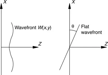
Figure 1.1 Two interfering wavefronts.
To study the main principles of interferometers, let us consider a two-wave interferogram with a flat wavefront that has a positive tilt about the y-axis and a wavefront under analysis, for which the deformations with respect to a flat wavefront without tilt are given by W(x, y). This tilt is said to be positive when the wavefront is as shown in Figure 1.1. The complex amplitude in the observation plane, where the two wavefronts interfere, is the sum of the complex amplitudes of the two waves as follows:
(1.1) |
where A1 is the amplitude of the light beam at the wavefront under analysis, A2 is the amplitude of the light beam with the reference wavefront, and k = 2π/λ. Hence, the irradiance is:
(1.2) |
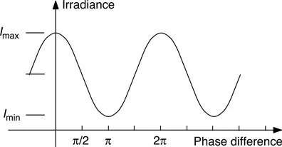
Figure 1.2 Irradiance as a function of phase difference between the two waves along the light path.
where the symbol * denotes the complex conjugate of the electric field. Here, we have introduced optional tilt θ about the y-axis between the two wavefronts. The irradiance function, I(x, y), may then be written as:
(1.3) |
where I1(x, y) and I2(x, y) are the irradiances of the two beams, and the phase difference between them is given by φ = k(xsinθ – W(x, y)). This function is shown graphically in Figure 1.2.
For convenience, Equation 1.3 is frequently written as:
(1.4) |
Assuming that the variations in the values of a(x, y) and b(x, y) inside the interferogram aperture are smoother than the variations of the cosine term, the maximum irradiance in the vicinity of the point (x, y) in this interferogram is given by:
(1.5) |
and the minimum irradiance in the same vicinity is given by:
(1.6) |
The fringe visibility, v(x, y), is defined by:
(1.7) |
Hence, we may find:
(1.8) |
Using the fringe visibility,...
Table of contents
- Cover
- Half Title
- Title Page
- Copyright Page
- Table of Contents
- Chapter 1 Review and Comparison of the Main Interferometric Systems
- Chapter 2 Fourier Theory Review
- Chapter 3 Digital Image Processing
- Chapter 4 Fringe Contouring and Polynomial Fitting
- Chapter 5 Periodic Signal Phase Detection and Algorithm Analysis
- Chapter 6 Phase-Detection Algorithms
- Chapter 7 Phase-Shifting Interferometry
- Chapter 8 Spatial Linear and Circular Carrier Analysis
- Chapter 9 Interferogram Analysis with Moiré Methods
- Chapter 10 Interferogram Analysis without a Carrier
- Chapter 11 Phase Unwrapping
- Chapter 12 Wavefront Curvature Sensing
- Index
Frequently asked questions
Yes, you can cancel anytime from the Subscription tab in your account settings on the Perlego website. Your subscription will stay active until the end of your current billing period. Learn how to cancel your subscription
No, books cannot be downloaded as external files, such as PDFs, for use outside of Perlego. However, you can download books within the Perlego app for offline reading on mobile or tablet. Learn how to download books offline
Perlego offers two plans: Essential and Complete
- Essential is ideal for learners and professionals who enjoy exploring a wide range of subjects. Access the Essential Library with 800,000+ trusted titles and best-sellers across business, personal growth, and the humanities. Includes unlimited reading time and Standard Read Aloud voice.
- Complete: Perfect for advanced learners and researchers needing full, unrestricted access. Unlock 1.4M+ books across hundreds of subjects, including academic and specialized titles. The Complete Plan also includes advanced features like Premium Read Aloud and Research Assistant.
We are an online textbook subscription service, where you can get access to an entire online library for less than the price of a single book per month. With over 1 million books across 990+ topics, we’ve got you covered! Learn about our mission
Look out for the read-aloud symbol on your next book to see if you can listen to it. The read-aloud tool reads text aloud for you, highlighting the text as it is being read. You can pause it, speed it up and slow it down. Learn more about Read Aloud
Yes! You can use the Perlego app on both iOS and Android devices to read anytime, anywhere — even offline. Perfect for commutes or when you’re on the go.
Please note we cannot support devices running on iOS 13 and Android 7 or earlier. Learn more about using the app
Please note we cannot support devices running on iOS 13 and Android 7 or earlier. Learn more about using the app
Yes, you can access Interferogram Analysis For Optical Testing by Zacarias Malacara,Manuel Servín in PDF and/or ePUB format, as well as other popular books in Physical Sciences & Physics. We have over one million books available in our catalogue for you to explore.