- 200 pages
- English
- ePUB (mobile friendly)
- Available on iOS & Android
eBook - ePub
About this book
With very few books adequately addressing ASME Boiler & Pressure Vessel Code, and other international code issues, Pressure Vessels: Design and Practice provides a comprehensive, in-depth guide on everything engineers need to know.
With emphasis on the requirements of the ASME this consummate work examines the design of pressure vessel com
Tools to learn more effectively

Saving Books

Keyword Search

Annotating Text

Listen to it instead
Information
Topic
Physical SciencesSubtopic
Thermodynamicschapter one
Overview of pressure vessels
1.1 Introduction
Vessels, tanks, and pipelines that carry, store, or receive fluids are called pressure vessels. A pressure vessel is defined as a container with a pressure differential between inside and outside. The inside pressure is usually higher than the outside, except for some isolated situations. The fluid inside the vessel may undergo a change in state as in the case of steam boilers, or may combine with other reagents as in the case of a chemical reactor. Pressure vessels often have a combination of high pressures together with high temperatures, and in some cases flammable fluids or highly radioactive materials. Because of such hazards it is imperative that the design be such that no leakage can occur. In addition these vessels have to be designed carefully to cope with the operating temperature and pressure. It should be borne in mind that the rupture of a pressure vessel has a potential to cause extensive physical injury and property damage. Plant safety and integrity are of fundamental concern in pressure vessel design and these of course depend on the adequacy of design codes.
When discussing pressure vessels we must also consider tanks. Pressure vessels and tanks are significantly different in both design and construction: tanks, unlike pressure vessels, are limited to atmospheric pressure; and pressure vessels often have internals while most tanks do not (and those that do are limited to heating coils or mixers).
Pressure vessels are used in a number of industries; for example, the power generation industry for fossil and nuclear power, the petrochemical industry for storing and processing crude petroleum oil in tank farms as well as storing gasoline in service stations, and the chemical industry (in chemical reactors) to name but a few. Their use has expanded throughout the world. Pressure vessels and tanks are, in fact, essential to the chemical, petroleum, petrochemical and nuclear industries. It is in this class of equipment that the reactions, separations, and storage of raw materials occur. Generally speaking, pressurized equipment is required for a wide range of industrial plant for storage and manufacturing purposes.
The size and geometric form of pressure vessels vary greatly from the large cylindrical vessels used for high-pressure gas storage to the small size used as hydraulic units for aircraft. Some are buried in the ground or deep in the ocean, but most are positioned on ground or supported in platforms. Pressure vessels are usually spherical or cylindrical, with domed ends. The cylindrical vessels are generally preferred, since they present simpler manufacturing problems and make better use of the available space. Boiler drums, heat exchangers, chemical reactors, and so on, are generally cylindrical. Spherical vessels have the advantage of requiring thinner walls for a given pressure and diameter than the equivalent cylinder. Therefore they are used for large gas or liquid containers, gas-cooled nuclear reactors, containment buildings for nuclear plant, and so on. Containment vessels for liquids at very low pressures are sometimes in the form of lobed spheroids or in the shape of a drop. This has the advantage of providing the best possible stress distribution when the tank is full.
The construction of a typical pressure vessel is shown in Figure 1.1. A spherical pressure vessel is shown in Figure 1.2. This is a special pressure vessel and is really a storage sphere. Functionally it acts as a tank because its purpose is to store a fluid. However since it does so at pressures above atmospheric, it can be classified as a pressure vessel. This however does not have internals and operates at atmospheric temperatures. A horizontally supported cylindrical pressure vessel with a hemispherical head and conical transition is shown in Figure 1.3. This consists of a cylindrical main shell, with hemispherical headers and several nozzle connections.
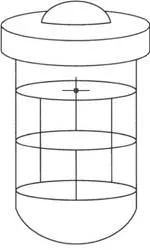
Figure 1.1 Typical pressure vessel.
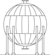
Figure 1.2 Spherical pressure vessel.
The vessel geometries can be broadly divided into plate- and shell-type configurations. The plate-type construction used in flat covers (closures for pressure vessels and heat exchangers) resists pressure in bending, while the shell-type’s membrane action operates in a fashion analogous to what happens in balloons under pressure. Generally speaking the shell-type construction is the preferred form because it requires less thickness (as can be demonstrated analytically) and therefore less material is required for its manufacture. Shell-type pressure components such as pressure vessel and heat exchanger shells, heads of different geometric configurations, and nozzles resist pressure primarily by membrane action.
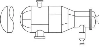
Figure 1.3 Horizontally supported pressure vessel.
Pressure vessels are made in all shapes and sizes, from a few centimeters (cm) in diameter to 50 meters (m) or more in diameter. The pressure may be as low as 0.25 kilopascals (kPa) to as high as 2000 megapascals (MPa). The American Society of Mechanical Engineers (ASME) Boiler and Pressure Vessel Code, Section VIII, Division 1,1 specifies a range of internal pressures from 0.1 MPa to 30 MPa. Pressure equipment, such as the American Petroleum Institute (API) storage tanks are designed to restrict internal pressure to no more than that generated by the static head of the fluid contained in the tank.
A few more examples are provided in this chapter. In the area of nuclear power generation a number of coolant systems are used. The two plant cycles most often found in nuclear power plants are the pressurized water reactor and the boiling water reactor. The pressurized water reactor inside the reactor pressure vessel is subjected to a high coolant water pressure. The pressurized water is heated and the pump circulates the water through a heat exchanger (steam generator) where the steam for the turbine is generated. The part of the nuclear power plant containing the reactor coolant is called the primary circuit. Included in the primary circuit is an important vessel called the pressurizer. The coolant volume varies when the load changes require reactor coolant temperature changes, and when this occurs, the pressurizer serves as the expansion tank in the primary system, which allows the water to undergo thermal expansion and contraction keeping the primary circuit pressure nearly constant. If the pressures are allowed to fluctuate too far, steam bubbles might form at the reactor heating surf aces; these bubbles or voids if formed inside the reactor core greatly alter reactor power output. The pressurizer has electric heating elements located low inside to provide the vapor needed to cushion the flowing liquid coolant. All of these items are included in the primary circuit. Figure 1.4 shows a pressurized water reactor (PWR) vessel. A PWR steam generator and a PWR pressurizer are indicated in Figures 1.5 and 1.6, respectively. The rest of the plant is called the secondary circuit. The steam generator produces the steam that passes through the turbine, condenser, condensate pumps, feed pump, feed water heaters and back to the steam generator.
Pressure vessels as components of a complete plant are designed to meet various requirements as determined by the designers and analysts responsible for the overall design. The first step in the design procedure is to select the necessary relevant information, establishing in this way a body of design requirements, as shown in Figure 1.7. Once the design requirements have been established, suitable materials are selected and the specified design code will give an allowable design or nominal stress that is used to dimension the main pressure vessel thickness. Additional code rules cover the design of various vessel components such as nozzles, flanges, and so on. Following these rules an arrangement of the various components are finalized and analyzed for failure. Most of the types of failure relevant to pressure vessel design are stress dependent and therefore it is necessary to ensure the adequacy of the stress distribution and check against different types of postulated failure modes. The proposed design is finally iterated until the most economical and reliable product is obtained. The functional requirements cover the geometrical design parameters such as size and shape, location of the penetrations, and so on. Some of these parameters may have to be fixed in collaboration with the overall design team, but in a majority of situations the pressure vessel designer acts freely on the basis of his or her experience.
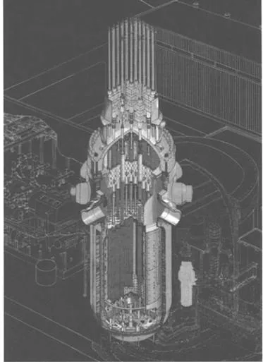
Figure 1.4 Pressurized water reactor (PWR) pressure vessel.
(Courtesy of Westinghouse Electric Company, Pittsburgh, PA.)
(Courtesy of Westinghouse Electric Company, Pittsburgh, PA.)
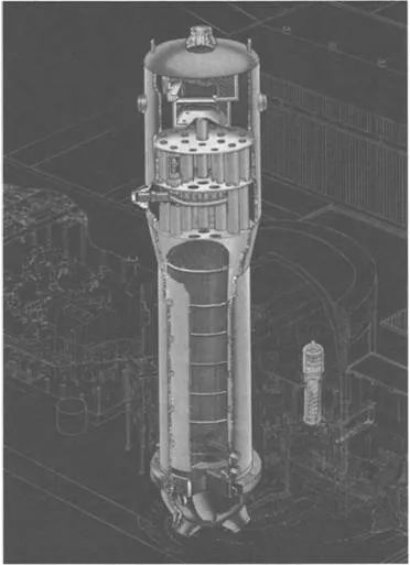
Figure 1.5 Pressurized water reactor (PWR) steam generator.
(Courtesy of Westinghouse Electric Company, Pittsburgh, PA.)
(Courtesy of Westinghouse Electric Company, Pittsburgh, PA.)
In the design of pressure vessels safety is the primary consideration, especially for nuclear reactor pressure vessels, due the potential impact of a possible severe accident. In general however, the design is a compromise between consideration of economics and safety. The possible risks of a given mode of failure and its consequences are balanced against the effort required for its prevention; the resulting design should achieve an adequate standard of safety at minimum cost.
Safety cannot be absolutely assured for two reasons. First, the actual form of loading during service may be more severe than was anticipated at the design stage: abnormal, unpredictable loads inevitably occur during the pressure vessel’s lifetime. Second, our knowledge is seldom adequate to provide a qualified answer to the fracture of materials, state of stress under certain conditions, and so on.
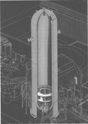
Figure 1.6 Pressurized water reactor (PWR) pressurizer.
(Courtesy of Westinghouse Electric Company, Pittsburgh, PA.)
(Courtesy of Westinghouse Electric Company, Pittsburgh, PA.)
It is true that although the fundamental mechanism of failure is not sufficiently understood, it is possible to establish preventive measures based on semiempirical methods. Following this line of thinking, the pressure vessels could be classified according to the severity of their operations since this will affect both the possibility of failure and its consequences. These considerations lead to the classification of vessels ranging from nuclear reactor pressure vessels at one end to underground water tanks at the other. The design factor used in the ASME Boiler and Pressure Vessel Code1 is intended to account for unknown factors associated with the design and construction of the equipment. The design formulas and the stress analysis methods are generally approximate and have built-in assumptions. Typically it is assumed that the material is homogeneous and isotropic. In the real world the material has flaws and discontinuities, which tend to deviate from this assumption.
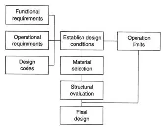
Figure 1.7 Design procedure.
In 1925, the rules for construction of power boilers was written using a design factor of 5 which was subsequently reduced to 4 in 1942, presumably to help conserve steel. In 1955, new processes in the petrochemical industry were requiring significant design pressures requiring wall thickness in vessels to be between 150 and 200 millimeters (mm). The ASME Pressure Vessel and Code Committee decided to form a task group with the allowable stresses based on a design factor of 3. The purpose was to reduce fabrication costs, with the implied assumptions that this could be applied to limited materials, with the addition of fracture toughness rules along with design rules for cyclic operation (fatigue) and that detailed stress analysis was used for most loading conditions.
The committee felt that the nuclear code for pressure vessels would be easier to write than the code for pressure vessels used in petrochemical processes. This is because the nuclear pressure vessels only contained steam and water, and the maximum temperature was 800°F (427°C). Many nuclear plant design specifications identified that the design cycles for fatigue evaluation should be based on a 40-year life expectancy of the plant. The 40 years was based on nuclear plants being able to last twice as long as fossil plants (which usually lasted 20 years). The design for cyclic operation was based on the estimated cycles for 40 years, with the severity of the cycles based on estimated worst conditions. This method of design was a rough attempt to ensure freedom from fatigue cracking during the 40-year period. Using the code fatigue curves, a cumulative usage factor was calculated that was arbitrarily required to be equal to less than unity, which is based on the estimated number of cycles for the postulated 40-year period. The methodology has many conservative design factors in it, namely a factor of 2 for stress and a 20 for cycles.
1.2 Development of pressure vessel construction codes
Numerous boiler explosions took place through the late 1800s and early 1900s. This led to the enactme...
Table of contents
- Cover Page
- Mechanical Engineering Series
- Title Page
- Copyright Page
- Preface
- Acknowledgments
- Chapter one: Overview of pressure vessels
- Chapter two: Pressure vessel design philosophy
- Chapter three: Structural design criteria
- Chapter four: Stress categories and stress limits
- Chapter five: Design of cylindrical shells
- Chapter six: Design of heads and covers
- Chapter seven: Design of nozzles and openings
- Chapter eight: Fatigue assessment of pressure vessels
- Chapter nine: Bolted flange connections
- Chapter ten: Design of vessel supports
- Chapter eleven: Simplified inelastic methods in pressure vessel design
- Chapter twelve: Case studies
- Appendix A: Review of solid mechanics
- Appendix B: Review of fatigue and fracture mechanics
- Appendix C: Limit analysis
Frequently asked questions
Yes, you can cancel anytime from the Subscription tab in your account settings on the Perlego website. Your subscription will stay active until the end of your current billing period. Learn how to cancel your subscription
No, books cannot be downloaded as external files, such as PDFs, for use outside of Perlego. However, you can download books within the Perlego app for offline reading on mobile or tablet. Learn how to download books offline
Perlego offers two plans: Essential and Complete
- Essential is ideal for learners and professionals who enjoy exploring a wide range of subjects. Access the Essential Library with 800,000+ trusted titles and best-sellers across business, personal growth, and the humanities. Includes unlimited reading time and Standard Read Aloud voice.
- Complete: Perfect for advanced learners and researchers needing full, unrestricted access. Unlock 1.4M+ books across hundreds of subjects, including academic and specialized titles. The Complete Plan also includes advanced features like Premium Read Aloud and Research Assistant.
We are an online textbook subscription service, where you can get access to an entire online library for less than the price of a single book per month. With over 1 million books across 990+ topics, we’ve got you covered! Learn about our mission
Look out for the read-aloud symbol on your next book to see if you can listen to it. The read-aloud tool reads text aloud for you, highlighting the text as it is being read. You can pause it, speed it up and slow it down. Learn more about Read Aloud
Yes! You can use the Perlego app on both iOS and Android devices to read anytime, anywhere — even offline. Perfect for commutes or when you’re on the go.
Please note we cannot support devices running on iOS 13 and Android 7 or earlier. Learn more about using the app
Please note we cannot support devices running on iOS 13 and Android 7 or earlier. Learn more about using the app
Yes, you can access Pressure Vessels by Somnath Chattopadhyay in PDF and/or ePUB format, as well as other popular books in Physical Sciences & Thermodynamics. We have over one million books available in our catalogue for you to explore.