- 1,048 pages
- English
- ePUB (mobile friendly)
- Available on iOS & Android
eBook - ePub
The PC Graphics Handbook
About this book
The PC Graphics Handbook serves advanced C++ programmers dealing with the specifics of PC graphics hardware and software.
Discussions address:
Tools to learn more effectively

Saving Books

Keyword Search

Annotating Text

Listen to it instead
Information
Part I
Graphics Fundamentals
Chapter 1
PC Graphics Overview
Topics:
- History and evolution of PC graphics
- Technologies
- Applications
- Development platforms
- The state-of-the-art
This first chapter is a brief historical summary of the evolution of PC graphics, a short list of graphics-related technologies and fields of application, and an overview of the state-of-the-art. A historical review is necessary in order to understand current PC graphics technologies. What the PC is today as a graphical machine is the result of a complex series of changes, often influenced by concerns of backward compatibility and by commercial issues. A review of graphics hardware technologies is also necessary because the graphics programmer usually works close to the metal. The hardware intimacy requires a clear understanding the how a binary value, stored in a memory cell, is converted into a screen pixel. The chapter also includes a description of some of the most important applications of computer graphics and concludes with a presentation of the graphics technologies and development platforms for the PC.
1.1 History and Evolution
The state-of-the-art computer is a graphics machine. It is typically equipped with a highresolution display, a graphics card or integral video system with 3D capabilities, and a processor and operating system that support a sophisticated graphical user interface. This has not always been the case. In the beginning computers were text-based. Their principal application was processing text data. The typical source of input was a typewriter-like machine called a teletype terminal or TTY. Output was provided by a line printer that operated by means of a mechanical arrangement of small pins that noisily produced an approximate rendering of the alphabetic characters. It was not until the 1960s that cathode-ray tube technology (CRT) found its way from television into computers. We start at this technological point.
1.1.1 The Cathode-Ray Tube
The CRT display consists of a glass tube whose interior is coated with a specially formulated phosphor. When the phosphor-coated surface is struck by an electron beam it becomes fluorescent. In computer applications CRT displays are classified into three groups: storage tube, vector refresh, and raster-scan.
The storage tube CRT can be used both as a display and as a storage device, since the phosphor image remains visible for up to 1 hour. To erase the image the tube is flooded with a voltage that turns the phosphor back to its dark state. One limitation is that specific screen areas cannot be individually erased. This determines that in order to make a small change in a displayed image, the entire CRT surface must be redrawn. Furthermore, the storage tube technology display has no color capabilities and contrast is low. This explains why storage tube displays have seldom been used in computers, and never in microcomputers.
Computers were not the first machines to use the cathode-ray tubes for graphic display. The oscilloscope, a common laboratory apparatus, performs operations on an input signal in order to display the graph of the electric or electronic wave on a fluorescent screen
The vector-refresh display, on the other hand, uses a short-persistence phosphor whose coating must be reactivated by the electron beam. This reactivation, called the refresh, takes place at a rate of 30 to 50 times per second. The vector-refresh system also requires a display file and a display controller. The display file is a memory area that holds the data and instructions for drawing the objects to be displayed. The display controller reads this information from the display file and transforms it into digital commands and data which are sent to the CRT. Figure 1–1 shows the fundamental elements of a vector refresh display system.
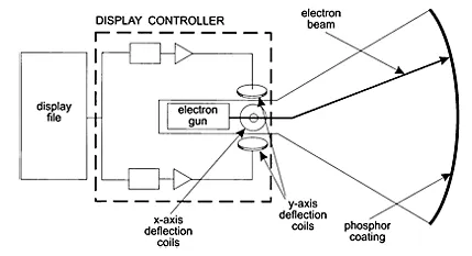
Figure 1–1 Vector-Refresh Display
The disadvantages of the vector-refresh CRT are its high cost and limited color capabilities. Vector refresh display technology has not been used in the PC.
During the 1960s Conrac Corporation developed a computer image processing technology, known as raster-scan graphics. Their approach took advantage of the methods of image rendering and refreshing used in television receivers. In a raster-scan display the electron beam follows a horizontal line-by-line path, starting at the top-left corner of the CRT surface. The scanning cycle takes place 50 to 70 times per second. At the start of each horizontal line the controller turns on the electron beam. The beam is turned off during the horizontal and vertical retrace cycles. The scanning path is shown in Figure 1–2.
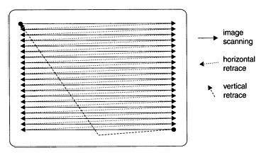
Figure 1–2 A Raster-Scan System
The raster-scan display surface is divided into a grid of individual dots, called pixels. The term pixel was derived from the words picture and elements. In the memory-mapped implementation of raster-scan technology, an area of RAM is devoted to recording the state of each individual screen pixel. The simplest color-coding scheme consists of using a single bit to represent either a white or a black pixel. Conventionally, if the memory bit is set, the display scanner renders the corresponding pixel as white. If the memory bit is cleared, the pixel is left dark. The area of memory reserved for the screen display is usually called the frame buffer or the video buffer. Figure 1–3, on the following page, shows the elements of a memory-mapped video system.
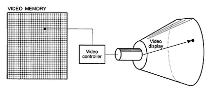
Figure 1–3 A Memory-Mapped System
Implementing color pixels requires a more elaborate scheme. In color systems the CRT is equipped with one electron gun for each color that is used to activate the pixels. Usually there are three color-sensitive electron guns: one for red, one for green, and one for blue. Data for each of the three colors must be stored separately. One approach is to have a separate memory map for each color. A more common solution is to devote bit fields or storage units to each color. For example, if one memory byte is used to encode the pixel’s color attributes, three bits can be assigned to encode the red color, two bits to encode the green color, and three bits for the blue color. One possible mapping of colors to pixels is shown in Color Figure 1.
In Color Figure 1 one memory byte has been divided into three separate bit fields. Each bit field encodes the color values that are used to render a single screen pixel. The individual bits are conventionally labeled with the letters R, G, and B, according to the color they represent. Since eight combinations can be encoded in a three-bit field, the blue and red color components can each have eight levels of intensity. In this example we have used a two-bit field to encode the green color; therefore it can only be rendered in four levels of intensity. The total number of combinations that can be encoded in 8 bits is 256, which is also the number of different color values that can be represented in one memory byte. The color code is transmitted by the display controller hardware to a Digital-to-Analog converter (DAC), which, in turn, transmits the color video signals to the CRT.
In the PC all video systems are raster-scan and memory mapped. The advantages of a raster-scan display are low cost, color capability, and easy programmability. One major disadvantage is the grainy physical structure of the display surface that results from the individual screen dots. Among other aberrations, the dot pattern causes lines that are not vertical, horizontal, or at exactly 45 degrees to exhibit a staircase effect. Raster-scan systems also have limitations in rendering animation. Two factors contribute to this problem: first, all the screen pixels within a rectangular area must be updated with each image change. Second, in order to ensure smoothness, the successive images that create the illusion of motion must be flashed on the screen at a fast rate. These constraints place a large processing load on the microprocessor and the display system hardware.
1.2 Short History of PC Video
The original IBM Personal Computer was offered in 1981 equipped with either a Monochrome Display Adapter (MDA), or a graphics system named the Color/Graphics Monitor Adapter (CGA). The rationale for having two different display systems was that users who intended to use the PC for text operations would prefer a machine equipped with the MDA video system, while those requiring graphics would like one equipped with the CGA card. But, in reality, the CGA graphics system provided only the most simple and unsophisticated graphics. The card was also plagued with interference problems which created a screen disturbance called “snow.” However, the fact that the original IBM Personal Computer was furnished with an optional graphics system signaled that the industry considered video graphics as an essential part of microcomputing.
During the past 20 years PC video hardware has been furnished in an assortment of on-board systems, plug-in cards, monitors, and options manufactured and marketed by many companies. In the following sections we briefly discuss better known PC video systems. Systems that were short lived or that gained little popularity, such as the PCJr, the IBM Professional Graphics Controller, the Multicolor Graphics Array, and the IBM Image Adapter A, are not mentioned.
1.2.1 Monochrome Display Adapter
The original alphanumeric display card designed and distributed by IBM for the Personal Computer was sold as the Monochrome Display and Printer Adapter since it included a parallel printer port. The MDA could display the entire range of alphanumeric and graphic characters in the IBM character set, but did not provide pixel-level graphics functions. The MDA was compatible with the IBM PC, PC XT, and PC AT, and some of the earlier models of the PS/2 line. It could not be used in the PCjr, the PC Convertible, or in the microchannel PS/2 machines. The card required a special monochrome monitor of long-persistence (P39) phosphor. These monitors, which produced very pleasant text, were available with either green or amber screens. The video hardware was based on the Motorola 6845 CRT controller. The system contained 4K of on-board video memory, mapped to physical address B0000H.
The MDA was designed as a pure alphanumeric display: the programmer could not access the individual screen pixels. Video memory is mapped as a grid of character and attribute bytes. The character codes occupy the even-numbered bytes in adapter memory, and the display attributes the odd-numbered bytes. This special storage and display scheme was conceived to save memory space and to simplify programming. Figure 1–4 shows the cell structure of the MDA video memory space and the bitmap for the attribute cells.
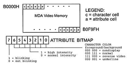
Figure 1–4 Memory Mapping and Attributes in the MDA Adapter
1.2.2 Hercules Graphics Card
An aftermaket version of the MDA, developed and marketed by Hercules Computer Technologies, was called the Hercules Graphics Card (HGC). HGA emulates the monochrome functions of the MDA, but can also operate in a graphics mode. Like the MDA, the HGC includes a parallel printer port. Because of its graphics capabilities, the Hercules card was often preferred over the IBM version. In the HGA the display buffer consists of 64K of video memory. In alphanumeric mode the system sees only the 4K required for text mode number 7. However, when the HGC is in the graphics mode, the 64K are partitioned as two 32K graphics pages located at physical addresses B0000H to B7FFFH and B80...
Table of contents
- Cover Page
- Title Page
- Copyright Page
- List of Tables
- List of Illustrations
- Preface
- Part I: Graphics Fundamentals
- Part II: DOS Graphics
- Part III: Windows API Graphics
- Part IV: DirectX Graphics
- Appendix A: Windows Structures
- Appendix B: Ternary Raster Operation Codes
- Bibliography
Frequently asked questions
Yes, you can cancel anytime from the Subscription tab in your account settings on the Perlego website. Your subscription will stay active until the end of your current billing period. Learn how to cancel your subscription
No, books cannot be downloaded as external files, such as PDFs, for use outside of Perlego. However, you can download books within the Perlego app for offline reading on mobile or tablet. Learn how to download books offline
Perlego offers two plans: Essential and Complete
- Essential is ideal for learners and professionals who enjoy exploring a wide range of subjects. Access the Essential Library with 800,000+ trusted titles and best-sellers across business, personal growth, and the humanities. Includes unlimited reading time and Standard Read Aloud voice.
- Complete: Perfect for advanced learners and researchers needing full, unrestricted access. Unlock 1.4M+ books across hundreds of subjects, including academic and specialized titles. The Complete Plan also includes advanced features like Premium Read Aloud and Research Assistant.
We are an online textbook subscription service, where you can get access to an entire online library for less than the price of a single book per month. With over 1 million books across 990+ topics, we’ve got you covered! Learn about our mission
Look out for the read-aloud symbol on your next book to see if you can listen to it. The read-aloud tool reads text aloud for you, highlighting the text as it is being read. You can pause it, speed it up and slow it down. Learn more about Read Aloud
Yes! You can use the Perlego app on both iOS and Android devices to read anytime, anywhere — even offline. Perfect for commutes or when you’re on the go.
Please note we cannot support devices running on iOS 13 and Android 7 or earlier. Learn more about using the app
Please note we cannot support devices running on iOS 13 and Android 7 or earlier. Learn more about using the app
Yes, you can access The PC Graphics Handbook by Julio Sanchez,Maria P. Canton in PDF and/or ePUB format, as well as other popular books in Computer Science & Computer Graphics. We have over one million books available in our catalogue for you to explore.