- 488 pages
- English
- ePUB (mobile friendly)
- Available on iOS & Android
eBook - ePub
Structural Design of Steelwork to EN 1993 and EN 1994
About this book
This is a solid introduction to design to the new Eurocode specification for civil and structural engineering students, technicians and professionals. It covers Eurocode 3 on steel and Eurocode 4 on composite structures, using worked examples, and provides introduction to principles and practical guidance on compliance.
Trusted by 375,005 students
Access to over 1.5 million titles for a fair monthly price.
Study more efficiently using our study tools.
Information
Chapter 1 / General
1.1 DESCRIPTION OF STEEL STRUCTURES
1.1.1 Shapes of Steel Structures
The introduction of structural steel, circa 1856, provided an additional building material to stone, brick, timber, wrought iron and cast iron. The advantages of steel are high strength, high stiffness and good ductility combined with relative ease of fabrication and competitive cost. Steel is most often used for structures where loads and spans are large and therefore is not often used for domestic architecture.
Steel structures include low-rise and high-rise buildings, bridges, towers, pylons, floors, oil rigs, etc. and are essentially composed of frames which support the self-weight, dead loads and external imposed loads (wind, snow, traffic, etc.). For convenience load bearing frames may be classified as:
(a) Miscellaneous isolated simple structural elements (e.g. beams and columns) or simple groups of elements (e.g. floors).
(b) Bridgeworks.
(c) Single storey factory units (e.g. portal frames).
(d) Multi-storey units (e.g. tower blocks).
(e) Oil rigs.
A real structure consists of a load bearing frame, cladding and services as shown in Fig. 1.1(a). A load bearing frame is an assemblage of members (structural elements) arranged in a regular geometrical pattern in such a way that they interact through structural connections to support loads and maintain them in equilibrium without excessive deformation. Large deflections and distortions in structures are controlled by the use of bracing which stiffens the structure and can be in the form of diagonal structural elements, masonry walls, reinforced concrete lift shafts, etc. A load bearing steel frame is idealized, for the purposes of structural design, as center lines representing structural elements which intersect at joints, as shown in Fig. 1.1(b). Other shapes of load bearing frames are shown in Figs 1.1 (c) to (e).
Structural elements are required to resist forces and displacements in a variety of ways, and may act in tension, compression, flexure, shear, torsion or in any combination of these forces. The structural behaviour of a steel element depends on the nature of the forces, the length and shape of the cross section of the member, the elastic properties and the magnitude of the yield stress. For example a tie behaves in a linear elastic manner until yield is reached. A slender strut behaves in a non-linear elastic manner until first yield is attained, provided that local buckling does not occur first. A laterally supported beam behaves elastically until a plastic hinge forms, while an unbraced beam fails by elastic torsional buckling. These modes of behaviour are considered in detail in the following chapters.
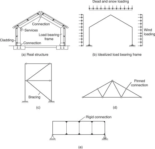
FIGURE 1.1 Typical load bearing frames
The structural elements are made to act as a frame by connections. These are composed of plates, welds and bolts which are arranged to resist the forces involved. The connections are described for structural design purposes as pinned, semi-rigid and rigid, depending on the amount of rotation, and are described, analysed and designed in detail in Chapter 7.
1.1.2 Standard Steel Sections
The optimization of costs in steel construction favours the use of structural steel elements with standard cross-sections and common bar lengths of 12 or 15 m. The billets of steel are hot rolled to form bars, flats, plates, angles, tees, channels, I sections and hollow sections as shown in Fig. 1.2. The detailed dimensions of these sections are given in BS 4, Pt 1 (2005), BSEN 10056-1 (1990), and BSEN 10210-2 (1997).
Where thickness varies, for example, Universal beams, columns and channels, sections are identified by the nominal size, that is, ‘depth × breadth × mass per unit length × shape’. Where thickness is constant, for example, tees and angle sections, the identification is ‘breadth × depth × thickness × shape’. In addition a section is identified by the grade of steel.
To optimize on costs steel plates should be selected from available stock sizes. Thicknesses are in the range of 6, 8, 10, 12,5, 15 mm and then in 5 mm increments. Thicknesses of less than 6 mm are available but because of lower strength and poorer corrosion resistance their use is limited to cold formed sections. Stock plate widths are in the range 1, 1,25, 1, 5, 2, 2, 5 and 3 m, but narrow plate widths are also available. Stock plate lengths are in the range 2, 2,5, 3, 4, 5, 6, 10 and 12 m. The adoption of stock widths and lengths avoids work in cutting to size and also reduces waste.
The application of some types of section is obvious, for example, when a member is in tension a round or flat bar is the obvious choice. However, a member in tension may be in compression under alternative loading and an angle, tee, or tube is often more appropriate. The connection at the end of a bar or tube, however, is more difficult to make.
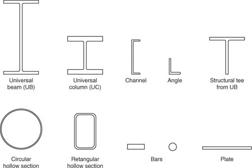
FIGURE 1.2 Standard steel section
If a structural element is in bending about one axis then the ‘I’ section is the most efficient because a large proportion of the material is in the flanges, that is, at the extreme fibres. Alternatively, if a member is in bending about two axes at right angles and also supports an axial load then a tube, or rectangular hollow section, is more appropriate.
Other steel sections available are cold formed from steel plate into a variety of cross sections for use as lightweight lattice beams, glazing bars, shelf racks, etc. Not all these sections are standardized because of the large variety of possible shapes and uses, however, there is a wide range of sections listed in BSEN 10162 (2003). Local buckling can be a problem and edges are stiffened using lips. Also when used as beams the relative thinness of the material may lead to web crushing, shear buckling and lateral torsional buckling. Although the thickness of the material (1–3 mm) is less than that of the standard sections the resistance to corrosion is good because of the surface finish obtained by pickling and oiling. After degreasing this surface can be protected by galvanizing, or painting, or plastic coating. The use in building of cold formed sections in light gauge plate, sheet and strip steel 6 mm thick and under is dealt with in BSEN 5950 (2001) and EN 1993-1-1 (2005).
1.1.3 Structural Classification of Steel Sections (cl 5.5. EN 1993-1-1 (2005))
A section, or element of a member, in compression due to an axial load may fail by local buckling. Local buckling can be avoided by limiting the width to thickness ratios (b/tf or d/tw) of each element of a cross-section. The use of the limiting values given in Table 5.2, EN 1993-1-1 (2005) avoids tedious and complicated calculations.
Depending on the b/tf or d/tw ratios standard or built-up sections are classified for structural purposes as:
• Class 1: Low values of b/tf or d/tw where a plastic hinge can be developed with sufficient rotation capacity to allow redistribution of moments within the structure.
• Class 2: Full plastic moment capacity can be developed but local buckling may prevent development of a plastic hinge with sufficient rotation capacity to permit plastic design.
• Class 3: High values of b/tf and d/tw, where stress at the extreme fibres can reach design strength but local buckling may prevent the development of the full plastic moment.
• Class 4: Local buckling may prevent the stress from reaching the design strength. Effective widths are used to allow for local buckling (cl 5.5.2(2), EN 1993-1-1 (2005)).
1.1.4 Structural Joints (EN 1993-1-8 (2005))
Structural elements are connected together at joints which are not necessarily at the ends of members. A structural connection is an assembly of components (plates, bolts, welds, etc.) arranged to transmit forces from one member to another. A connection may be subject to any combination of axial force, shear force and bending moment in relation to three perpendicular axes, but for simplicity, where appropriate, the situation is reduced to forces in one plane.
There are other types of joints in structures which are not structural connections. For example a movement joint is introduced into a structure to take up the free expansion and contraction that may occur on either side of the joint due to temperature, shrinkage, expansion, creep, settlement, etc. These joints may be detailed to be watertight but do not generally transmit forces. Detailed recommendations are given by Alexander and Lawson (1981). Another example is a construction joint which is introduced because components are manufactured to a convenient size for transportation and need to be connected together on site. In some cases these joints transmit forces but in other situations may only need to be waterproof.
1.2 DEVELOPMENT,MANUFACTURE AND TYPES OF STEEL
1.2.1 Outline of Developments in Design Using Ferrous Metals
Prior to 1779, when the Iron Bridge at Coalbrookdale on the Severn was completed, the most important materials used for load bearing structures were masonry and timber. Ferrous materials were only used for fastenings, armaments and chains.
The earliest use of cast iron columns in factory buildings (circa 1780) enabled relatively large span floors to be constructed. Due to a large number of disastrous fires around 1795, timber beams were replaced by cast iron with the floors carried on brick jack arches between the beams. This mode of construction was pioneered by Strutt in an effort to attain a fire proof construction technique.
Cast iron, however, is weak in tension and necessitates a tension flange larger than the compression flange and consequently cast iron was used mainly for compression members. Large span cast iron beams were impractical, and on occasions disastrous as in the collapse of the Dee bridge designed by Robert Stephenson in 1874. The last probable use of cast iron in bridge works was in the piers of the Tay bridge in 1879 when the bridge collapsed in high winds due to poor design and unsatisfactory supervision during construction.
In an effort to overcome the tensile weakness of cast iron, wrought iron was introduced in 1784 by Henry Cort. Wrought iron enabled the Victorian engineers to produce the following classic structures. Robert Stephenson's Brittania Bridge was the first box girder bridge and represented the first major collaboration between engineer, fabricator (Fairburn) and scientist (Hodgkinson). I.K. Brunel's Royal Albert Bridge at Saltash combined an arch and suspension bridge. Telford's Menai suspension bridge used wrought iron chains which have sine been replaced by steel chains. Telford's Pont Cysyllte is a canal aqueduct near Llangollen. The first of the four structures was replaced after a fire in 1970. The introduction of wrought iron revolutionized ship building and enabled Brunel to produce the S.S. Great Britain.
Steel was first produced in 1740, but was not available in large quantities until Bessemer invented the converter in 1856. The first major structure to use the new steel exclusively was Fowler and Baker's railway bridge at the Firth of Forth. The first steel rail was rolled in 1857 and installed at Derby where it was still in use 10 years later. Cast iron rails in the same position lasted about 3 months. Steel rails were in regular production at Crewe under Ramsbottom from 1866.
By 1840 standard shapes in wrought iron, mainly rolled flats, tees an...
Table of contents
- Front Cover
- Half Title
- Title Page
- Copyright
- Contents
- Preface
- Acknowledgements
- Principal Symbols
- CHAPTER 1 General
- CHAPTER 2 Mechanical Properties of Structural Steel
- CHAPTER 3 Actions
- CHAPTER 4 Laterally Restrained Beams
- CHAPTER 5 Laterally Unrestrained Beams
- CHAPTER 6 Axially Loaded Members
- CHAPTER 7 Structural Joints
- CHAPTER 8 Frames and Framing
- CHAPTER 9 Trusses
- CHAPTER 10 Composite Construction
- CHAPTER 11 Cold-formed Steel Sections
- ANNEX
- INDEX
Frequently asked questions
Yes, you can cancel anytime from the Subscription tab in your account settings on the Perlego website. Your subscription will stay active until the end of your current billing period. Learn how to cancel your subscription
No, books cannot be downloaded as external files, such as PDFs, for use outside of Perlego. However, you can download books within the Perlego app for offline reading on mobile or tablet. Learn how to download books offline
Perlego offers two plans: Essential and Complete
- Essential is ideal for learners and professionals who enjoy exploring a wide range of subjects. Access the Essential Library with 800,000+ trusted titles and best-sellers across business, personal growth, and the humanities. Includes unlimited reading time and Standard Read Aloud voice.
- Complete: Perfect for advanced learners and researchers needing full, unrestricted access. Unlock 1.5M+ books across hundreds of subjects, including academic and specialized titles. The Complete Plan also includes advanced features like Premium Read Aloud and Research Assistant.
We are an online textbook subscription service, where you can get access to an entire online library for less than the price of a single book per month. With over 1.5 million books across 990+ topics, we’ve got you covered! Learn about our mission
Look out for the read-aloud symbol on your next book to see if you can listen to it. The read-aloud tool reads text aloud for you, highlighting the text as it is being read. You can pause it, speed it up and slow it down. Learn more about Read Aloud
Yes! You can use the Perlego app on both iOS and Android devices to read anytime, anywhere — even offline. Perfect for commutes or when you’re on the go.
Please note we cannot support devices running on iOS 13 and Android 7 or earlier. Learn more about using the app
Please note we cannot support devices running on iOS 13 and Android 7 or earlier. Learn more about using the app
Yes, you can access Structural Design of Steelwork to EN 1993 and EN 1994 by Lawrence Martin,John Purkiss in PDF and/or ePUB format, as well as other popular books in Technology & Engineering & Civil Engineering. We have over 1.5 million books available in our catalogue for you to explore.