- 266 pages
- English
- ePUB (mobile friendly)
- Available on iOS & Android
eBook - ePub
Millimetre-Wave Optics, Devices and Systems
About this book
The millimetre-wavelength region of the electromagnetic spectrum is increasingly exploited for a wide range of commercial, industrial, and military applications. Conventionally, this region is considered as lying "above" microwaves and "below" the infrared. Hence, in practice, millimetre-wave scientists have tended to pick and mix useful techniques on an empirical basis from both these areas.
Millimetre-Wave Optics, Devices and Systems describes the fundamental physics of the quasi-optical techniques, devices, and system design for instruments processing millimetre-wave signals. Relevant ideas from Gaussian beam mode theory and antenna and transmission line theory are brought together to show the underlying unity of optics and electronics. Aimed at advanced undergraduates and postgraduates as well as millimetre-wave, laser optics, antenna, and microwave engineers, this book will also be of interest to manufacturers of millimetre-wave and microwave equipment.
Tools to learn more effectively

Saving Books

Keyword Search

Annotating Text

Listen to it instead
Information
Topic
Physical SciencesSubtopic
Optics & LightChapter 1
Signal Transmission, Modes and Gaussian Beams
1.1 Waveguides and General Mode Properties
Conventional electronic instruments use wires to send signals from place to place. As the signal frequency rises, it becomes increasingly difficult to make wired systems which work well. This is because—as was mentioned in the Preface—the actual signal is transmitted as an electromagnetic field which moves along just outside the wire. Some of this field can, therefore, be radiated away or coupled onto any other nearby wires.
Changes in the potential of a wire can be detected as a varying force on nearby charges. Similarly, changes in current alter the surrounding magnetic field and may induce currents on other wires. These effects are normally dealt with in electronics as ‘stray’ capacitances and inductances. They mean that some of the power that we wish to transmit via a wire may fail to arrive at its intended destination because it has been diverted elsewhere. It may also mean that some of the variations in potential and current arriving at the signal destination are the result of unwanted signals coupled onto the wire.
In many cases the signal wavelengths are far larger than the lengths of the transmitting wires and we can think of variations in current and charge as being uniform along the wire. If the frequency is increased sufficiently (or the wire extended), this assumption ceases to be reliable. Then the potential and current may be seen to vary along the length of the wire, i.e. there is a noticeable electric and magnetic field variation along the wire. Both of these fields vary periodically in time at the signal frequency. Now the wire will act as an antenna, radiating some signal power into the surrounding space.
As a result of these effects the efficiency of signal coupling along a wire tends to fall as the frequency rises. Various measures can be adopted to try to counteract these problems. One of the most useful is to replace the wires with a metallic waveguide. Although mainly used at microwave frequencies the metal waveguide is worth discussing in some detail here as it is used in many millimetre-wave systems and components. Many of the properties of waves propagating in waveguides of this type also turn out to be applicable in general to other forms of waveguide and to beams in space.
If we regard a normal wire as a length of metal surrounded by space, we can think of a metal waveguide as a length of space surrounded by metal. As with the wire, signal power is transmitted as an electromagnetic wave which moves along in the space outside the metal, i.e. the wave moves down the hole in the centre of the guide.
The most common form of waveguide is rectangular in cross section. Consider figure 1.1 which represents a rectangular guide.
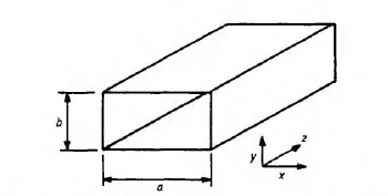
Figure 1.1 Short piece of rectangular waveguide.
In order to determine the field pattern inside the waveguide, we have to find the appropriate solution for Maxwell’s equations. We need to know at least some of the field components at some point within the guide. How can we do this for a rectangular metal waveguide?
A rectangular waveguide can be regarded simply as a set of four mirrors placed so as to form a long metal box with open ends. With this in mind we can understand its behaviour by considering what happens when an electromagnetic wave is incident upon a metal surface.
An incident wave sets up a current in a thin layer at the surface. If the wave is plane parallel moving perpendicular to the surface, then the current distribution is uniform over the surface. Hence there will be no net accumulation of charge at any point on the surface. No potential differences are produced and the total electric field along the surface must remain zero everywhere.
The velocity of light inside a metal is generally far lower than in free space, i.e. the refractive index is very high. Hence very little of the incident wave penetrates into the metal. In order for the incident energy not to vanish mysteriously it must be reflected. As the total electric field along the surface must be zero, it follows that the incident and reflected waves have electric field components parallel to the surface which are equal and opposite.
A wave incident upon a metal surface at an angle can be regarded as a combination of two waves arriving simultaneously—one perpendicular to the surface, and the other parallel to the surface. The effect of the perpendicular wave is as described. The behaviour of the wave moving parallel to the surface depends upon the orientation of its electric field with r...
Table of contents
- Cover
- Half Title
- Title Page
- Copyright Page
- Dedication
- Table of Contents
- Preface
- 1 Signal transmission, modes and Gaussian beams
- 2 Beam coupling, lenses and mirrors
- 3 Multi-mode beams and apertures
- 4 Antennas and feed systems
- 5 Transmission lines, impedance matching and signal reflections
- 6 Bolometric signal detection
- 7 Mixers and heterodyne detection
- 8 Filters and resonators
- 9 The Martin-Puplett interferometer
- 10 The design of optical circuits
- 11 Oscillators and signal sources
- 12 Frequency control loops and diplexers
- Appendices
- Further reading and selected references
- Index
Frequently asked questions
Yes, you can cancel anytime from the Subscription tab in your account settings on the Perlego website. Your subscription will stay active until the end of your current billing period. Learn how to cancel your subscription
No, books cannot be downloaded as external files, such as PDFs, for use outside of Perlego. However, you can download books within the Perlego app for offline reading on mobile or tablet. Learn how to download books offline
Perlego offers two plans: Essential and Complete
- Essential is ideal for learners and professionals who enjoy exploring a wide range of subjects. Access the Essential Library with 800,000+ trusted titles and best-sellers across business, personal growth, and the humanities. Includes unlimited reading time and Standard Read Aloud voice.
- Complete: Perfect for advanced learners and researchers needing full, unrestricted access. Unlock 1.4M+ books across hundreds of subjects, including academic and specialized titles. The Complete Plan also includes advanced features like Premium Read Aloud and Research Assistant.
We are an online textbook subscription service, where you can get access to an entire online library for less than the price of a single book per month. With over 1 million books across 990+ topics, we’ve got you covered! Learn about our mission
Look out for the read-aloud symbol on your next book to see if you can listen to it. The read-aloud tool reads text aloud for you, highlighting the text as it is being read. You can pause it, speed it up and slow it down. Learn more about Read Aloud
Yes! You can use the Perlego app on both iOS and Android devices to read anytime, anywhere — even offline. Perfect for commutes or when you’re on the go.
Please note we cannot support devices running on iOS 13 and Android 7 or earlier. Learn more about using the app
Please note we cannot support devices running on iOS 13 and Android 7 or earlier. Learn more about using the app
Yes, you can access Millimetre-Wave Optics, Devices and Systems by J.C.G Lesurf in PDF and/or ePUB format, as well as other popular books in Physical Sciences & Optics & Light. We have over one million books available in our catalogue for you to explore.