- 432 pages
- English
- ePUB (mobile friendly)
- Available on iOS & Android
eBook - ePub
Modern Digital Control Systems
About this book
This work presents traditional methods and current techniques of incorporating the computer into closed-loop dynamic systems control, combining conventional transfer function design and state variable concepts. Digital Control Designer - an award-winning software program which permits the solution of highly complex problems - is available on the CR
Tools to learn more effectively

Saving Books

Keyword Search

Annotating Text

Listen to it instead
Information
1
Introduction to Digital Control
1.1 THE BASIC IDEA OF SYSTEM CONTROL
The topic with which we deal in this book is that of the control of a dynamic system, the plant, by employing feedback which incorporates a digital computer in the control loop. A dynamic system is one that is described by differential equations, and as such the output variables will not exactly track the reference input variables.
Generally, this plant has continuous-in-time inputs and outputs. In general, the plant has r input variables (the control efforts) and m output variables. There may also be internal variables that are not outputs. Which variables are outputs is a matter for the system designer to decide. The control problem is one of manipulating the input variables in an attempt to influence the output variables in a desired fashion, for example, to achieve certain values or certain rates.
If we know the system model and the initial conditions with reasonable accuracy, we can manipulate the input variables so as to drive the outputs in the desired manner. This is what we would call open-loop control since it is accomplished without knowledge of the current outputs. This situation is depicted in Fig. 1.1. This type of control also assumes that the system operates in the absence of disturbances that would cause the system outputs to vary from those predicted by a model of the plant, which is seldom the case.
Because of uncertainties in the system model and initial conditions and because of disturbances there is a better way to accomplish the control task. This technique involves using sensors to measure the behavior of some subset of the output variables (those we want to control) y1(t), …, yk(t) (k ≤ m) and, after measurement, comparing them with what we would like each of them to be at time t and calling the difference between the desired value ri(t) and the measured value wi(t) the error. Using the errors in each of the variables, we can generate the control efforts so as to drive the errors toward zero. This situation, depicted in Fig. 1.2, is referred to as feedback control. Due to friction, inertia, and other dynamic properties, it is impossible to drive a system instantaneously to zero error. Thus the system outputs yi(t) will “lag” the desired outputs ri(t), and sometimes they will overshoot or oscillate about a zero error condition. Often, the dynamic character of available sensors makes the measurements not exactly true representations of the outputs.
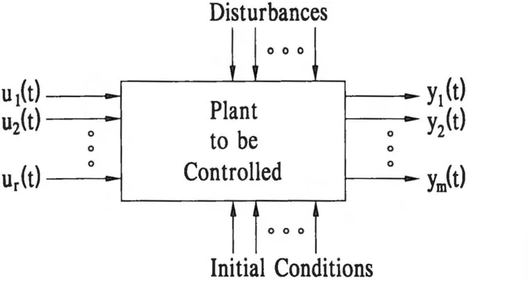
Figure 1.1. Open-loop-controlled plant.
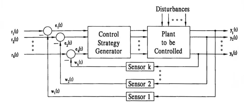
Figure 1.2. Feedback-controlled multivariable system with sensors.
For five decades the sensors and the synthesis of the control strategy generator have been the center of considerable engineering activity, and in general these devices are electrical or electromechanical in nature—more specifically, filters, amplifiers, power amplifiers, motors, and actuators. In all these cases the associated signals are continuous functions of the temporal variable t. We commonly refer to such systems as continuous-time control systems. As systems have become more and more complex with a multitude of control variables and output variables, the hardware synthesis job becomes a difficult task. Typical systems are airplane autopilot controls, chemical-processing controls, nuclear power plant controls, and a host of others generally involving large-scale systems.
With the advent of the digital computer, engineers began to explore the possibilities of having the computer keep track of the various signals and make logical decisions about control signals based on the measured signals and the desired values of the outputs. We know, however, that a digital computer is capable only of dealing with numbers and not signals, so if a digital computer is to accomplish the task, the sensor signals must be converted to numbers while the output control decisions must be output in the form of continuous-time signals. We discuss these conversion processes in Section 1.5. As an example, let us consider a single-loop position servomechanism in continuous form as shown in Fig. 1.3. The reference signal is in the form of a voltage, as is the feedback signal, both generated by mechanically driven potentiometers.
1.2 THE COMPUTER AS A CONTROL ELEMENT
Let us now investigate how this relatively simple task, outlined in Section 1.1, might be accomplished by employing a digital computer to generate the signal to the power amplifier. We must first postulate the existence of two devices. The first of these devices is the analog-to-digital (A/D) converter, which will sample the output signal periodically and convert these samples to digital words to be processed by the digital computer, which generates a control strategy in the form of a number. The second device is a digital-to-analog (D/A) converter, which converts the numerical control strategy generated by the digital computer from a digital word to an analog signal. The position servomechanism is shown in Fig. 1.4 controlled by a digital computer.
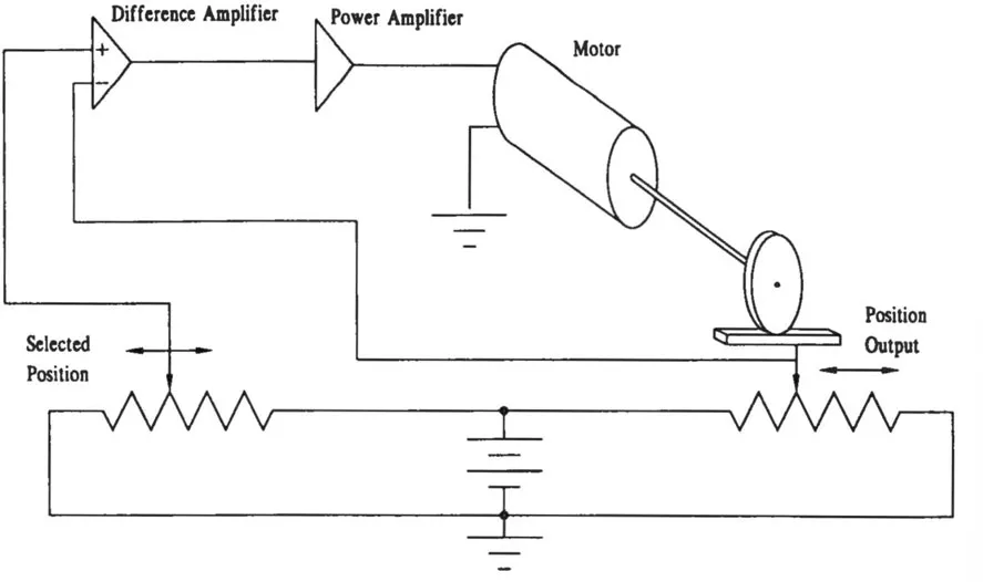
Figure 1.3. Position servomechanism with continuous signals.
This system was not chosen because it was realistic but rather to show the principle of digital control of a single-loop system. Generally, the A/D and D/A converters operate periodically, and hence the closer together in time the samples are taken and the more often the output of the D/A converter is updated, the closer the digital control system will approach the continuous-time system. As we shall learn later, it is not always desirable to have the system approach the continuous system in that there are desirable attributes to a discrete-time system. The limitation on the rate at which sampling can be done is that the sampled signal must be processed by the computer before the computer can drive the D/A converter with the new control strategy. Any algorithm to provide the control signal takes time to execute and hence limits the rate at which control effort update can occur. The general computer-controlled multivariable system is shown in Fig. 1.5.
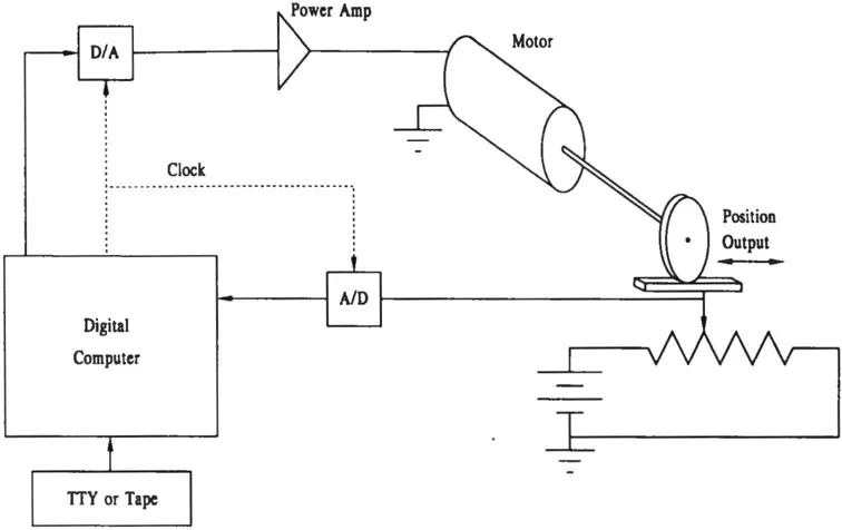
Figure 1.4. Digitally controlled positioning system.
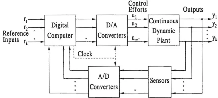
Figure 1.5. Digitally controlled multivariable system.
The engineering problems involved with the design and construction of digital control systems concern the design of faster and more accurate A/D and D/A converters and the synthesis of control algorithms to be executed by the digital computer. Other problems of engineering interest are those of quantization and of finite-word-length representation of numbers which in general require infinite-word-length representation.
Techniques have been established for designing the digital computer algorithm to obtain the best system performance given the dynamics of the plant to be controlled. Generally, the more system variables measured on which to base the control decisions, the better will be the degree of control.
1.3 SINGLE-LOOP DIGITAL CONTROL SYSTEM
Often, the problem is control of a single variable of a system which may have a multitude of other variables that are not necessarily to be controlled. There are several configurations of a single-loop control system, two of which are shown in Fig. 1.6a and b. In both cases a single continuous-time variable y(t) is being controlled to follow some reference signal r(t) which might be zero or constant, as in the case of a regulator.
The information leaving the digital computer in both cases is a sequence of numbers written periodically to the D/A converter which represent the control strategy as generated by the computer. The input to the digital computer is a periodic sequence of numbers that represent the samples taken periodically from the continuous signal that is input to the A/D converter. The purpose of developing a digital control theory is to be able to design desirable algorithms by which the digital computer converts the input sequence into the output sequence, which is the numerical control strategy. The design process is one of selecting the algorithm that reflects the function D(z), which we shall discuss at length in Chapters 3 and 4.
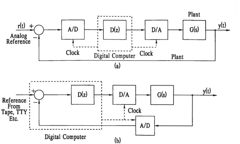
Figure 1.6. Several configurations of a digital control system.
1.4 WHY DIGITAL CONTROL INSTEAD OF ANALOG?
Since almost all control functions can be achieved with analog (continuous-time) hardware, one is tempted to ask why we might wish to study digital control the...
Table of contents
- Cover
- Half Title
- Title Page
- Copyright Page
- Dedication
- Table of Contents
- Preface to the Second Edition
- Preface to the First Edition
- 1 Introduction to Digital Control
- 2 Linear Difference Equations and the z-Transform
- 3 Elementary Digital Control System Design Using Transform Techniques
- 4 Advanced Digital Control System Design Techniques Employing the z-Transform
- 5 Digital Filtering and Digital Compensator Design
- 6 State-Variable Representation in Digital Control Systems
- 7 Quantization and Error Effects
- 8 State-Space Approach to Control System Design
- 9 Linear Discrete-Time Optimal Control
- 10 Discrete-Time Stochastic Systems
- 11 State Estimation in the Presence of Noise
- 12 Discrete-Time Stochastic Control Systems
- 13 Introduction to System Identification
- Appendix A Tables and Properties of z-Transforms
- Appendix B Algebraic Eigenvalue–Eigenvector Problem
- Appendix C Proof of the Matrix Inversion Lemma
- Appendix D Digital Control Designer
- Index
Frequently asked questions
Yes, you can cancel anytime from the Subscription tab in your account settings on the Perlego website. Your subscription will stay active until the end of your current billing period. Learn how to cancel your subscription
No, books cannot be downloaded as external files, such as PDFs, for use outside of Perlego. However, you can download books within the Perlego app for offline reading on mobile or tablet. Learn how to download books offline
Perlego offers two plans: Essential and Complete
- Essential is ideal for learners and professionals who enjoy exploring a wide range of subjects. Access the Essential Library with 800,000+ trusted titles and best-sellers across business, personal growth, and the humanities. Includes unlimited reading time and Standard Read Aloud voice.
- Complete: Perfect for advanced learners and researchers needing full, unrestricted access. Unlock 1.4M+ books across hundreds of subjects, including academic and specialized titles. The Complete Plan also includes advanced features like Premium Read Aloud and Research Assistant.
We are an online textbook subscription service, where you can get access to an entire online library for less than the price of a single book per month. With over 1 million books across 990+ topics, we’ve got you covered! Learn about our mission
Look out for the read-aloud symbol on your next book to see if you can listen to it. The read-aloud tool reads text aloud for you, highlighting the text as it is being read. You can pause it, speed it up and slow it down. Learn more about Read Aloud
Yes! You can use the Perlego app on both iOS and Android devices to read anytime, anywhere — even offline. Perfect for commutes or when you’re on the go.
Please note we cannot support devices running on iOS 13 and Android 7 or earlier. Learn more about using the app
Please note we cannot support devices running on iOS 13 and Android 7 or earlier. Learn more about using the app
Yes, you can access Modern Digital Control Systems by Jacquot,Raymond G. Jacquot in PDF and/or ePUB format, as well as other popular books in Technology & Engineering & Electrical Engineering & Telecommunications. We have over one million books available in our catalogue for you to explore.