- 168 pages
- English
- ePUB (mobile friendly)
- Available on iOS & Android
eBook - ePub
Principles of Element Design
About this book
The construction of buildings is learnt through experience and the inheritance of a tradition in forming buildings over several thousand years. Successful construction learns from this experience which becomes embodied in principles of application. Though materials and techniques change, various elements have to perform the same function. 'Principles of Element Design' identifies all the relevant elements and then breaks these elements down into all their basic constituents, making it possible for students to fully understand the given theory and principles behind each part. As all building projects are subject to guidance through the Building Regulations and British Standards, this book gives an immediate reference back to relevant information to help practitioners and contractors identify key documents needed.
Yvonne Dean B.A. (Hons) B.A (Open) RIBA, an architect, energy consultant and materials technologist. She also has 15 years experience as a lecturer, travels widely and is a guest lecturer at many universities. She pioneered an access course for Women into Architecture and Building, which has been used as a template by others, and has been instrumental in helping to change the teaching of technology for architects and designers.
Peter Rich AA Dipl. (Hons) Architect, started his career with 14 years experience as a qualified architectural technician. He then joined the AA School of Architecture, working with Bill Allen and John Bickerdike after his graduation, later becoming a partner of Bickerdike Allen Rich and Partners. He also taught building construction at the Bartlett School of Architecture, University College London, and architectural design at the Polytechnic of North London. He now acts as a Consultant.
Tools to learn more effectively

Saving Books

Keyword Search

Annotating Text

Listen to it instead
Information
Foundations: General Section 1
SMM7 D Groundwork, E In situ concrete, J Waterproofing
(See Section 2 for foundations in detail)
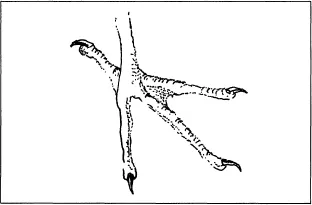
Heron’s foot
A number of animals and insects have to spread the load of their body over fragile surfaces. Birds in watery habitats have large feet, snow hares and polar bears spread their body weight over large soft pads.
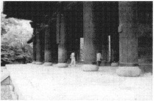
Japanese temple-posts on stone bases (Rich).
Notes and references
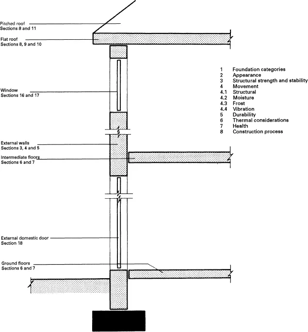
Numbered sections are cross-referenced from the diagrams and include comments followed, where appropriate, by technical references and relevant Building Regulations. Addresses of relevant trade and research organizations are listed at the end of the section. British Standards and BRE Digests should always be checked for current amendments. This section contains sub-sections 1 to 8, general factors. Greater detail is contained in Foundations in Detail Section 2.
General references
Mitchell’s Building Series: Structure and Fabric, Part 1, Chapter 4, Jack Stroud Foster, Structure and Fabric, Part 2, Chapter 3, Jack Stroud Foster. Longman, 1994.
Specification 1995: Building Methods & Products, Architectural Press. Available on CD-ROM.
Foundation Design and Construction, M. J. Tomlinson. Pitman, 1995.
Lost Rivers of London, N. J. Barton. Phoenix House, 1962.
Dampness in Buildings: The Professional’s and Homeowner’s guide. T. A. Oxley and E. G. Gobert. Butterworth-Heinemann, 1994.
1 Foundation categories
At an early design stage of a building, consideration must be given to the interrelationship between the building form (plan, shape, loads, disposition and method of transmitting forces), the characteristics of the supporting ground under the building and its allowable bearing pressure. Subsoils should be considered as reacting dynamically to load and seasonal changes with the ability not only to compress under load but also able to heave and swell. The focus of this interrelationship is in the foundations of the building and this section covers the general design principles of the four main categories:
1 Strip and deep strip foundations for transmitting the loads of continuous walls to the ground;
2 Pad or slab foundations for transmitting the point loads from columns and piers to the ground;
3 Raft foundations for transmitting the combined loads of the whole building to the ground;
4 Piled foundations under beams for continuous walls or under piers or columns in order to transmit their loads to a greater depth than would be feasible with other forms of foundations.
| Key Factors | Action | Counteraction |
| Gravity | Downward pull | Support |
| Wind | Motive force (eccentric | Design accommodation, |
| loading) | reduction | |
| Water | Causes erosion, frost heave | Design accommodation, |
| elimination | ||
| Sun | Ground shrinkage and | Design accommodation, |
| decomposition | protection | |
| Chemicals | Erosion | Design accommodation, reduction, elimination |
| Vibration | Settlement | Design accommodation, reduction, elimination |
2 Appearance
Appearance is not normally a deciding factor in the choice of foundation type although care should be taken where they are exposed to view, e.g. certain raft edge details – see example in Section 2.
3 Structural strength and stability
The function of a foundation is to spread the total loads acting on a building being chiefly dead or self loads, live loads, and wind loads (see Floors: General, Section 6, item 3 for definitions) as well as the weight of the foundation itself to the supporting ground. This must be achieved economically, safely and not cause excessive or unequal consolidation of the soil particles which could result in settlement, cracking, or even complete building collapse. The strength or resistance of the ground to the downward force of the building load is dependent upon the type, condition and likely behaviour under load of the soil particles on which the foundation rests.
Soil engineering is beyond the scope of this section but underneath the top layer of soil, which consists of decaying vegetable matter and has little strength, are bearing soils of varying strengths according to their particle size and other factors such as moisture content and consistency. Typical bearing capacities for various soils are given in BS 8004:1986 (Foundations and substructures for non-industrial buildings of not more than four storey) and range from 600 kN/m2 for certain gravels to less than 300 kN/m2 for soft clays and 75 kN/m2 for silts. See also BS 8103:1986 and BS 1377 Part 2:1990, Classification tests (for soils).
Detailed analysis of the soil is necessary as part of the first steps in the design process of the building structure since this will have a profound effect on the feasibility of a particular building form and the subsequent foundation type (see Foundation categories above). Soil investigations can be carried out with the assistance of some or all of the following methods:
1 Reference to geological, hydrogeological and topographical maps at the Institute of Geological Sciences, Exhibition Road, South Kensington, London SW7. These should be supplemented by information on climate from the Meteorological Office and, when building near coastal areas, by using Admiralty charts and publications which indicate high and low water marks or the levels of river beds. Contact the British Geological Survey, Kingsley Dunham Centre, Keyworth, Nottingham, NG12 5GG (tel. 0115-936 3241, fax 0115-936 3488) for a catalogue of all maps, specialist and technical reports on geology, hydrogeology and mineral resources. Most local libraries usually carry copies of detailed geological maps for the area and often hydrology maps too.
2 Empirical knowledge from local builders and officials, such as a local council’s building inspectors.
3 Trial holes and excavations. These are potentially dangerous areas unless well strutted and protected. They should be formed in accordance with BS 8000 Part 1:1989, Code of practice for excavation and filling, and the CIRIA (Construction Information and Research) publication on Trenching Practice (R 97). See also the Health and Safety Executive booklet, A Guide for Small Contractors (HS(G)46). Depending on the layout and form of building, trial holes should not be formed further apart than 30 m and not less than one per 930 m2 of site (Mitchell, Structure and Fabric, Part 1). Relative to soil type they are considered to be economical up to a depth of about 2 to 3 m and allow the exposed soil to be identified by simple visual, tactile or physical field tests.
4 Unlined hand-bored holes 100–150 mm diameter and lined hand-bored holes up to 200 mm diameter which are considered economical in softer soils up to a depth of 9 m and 24 m respectively (using a tackle and winch).
5 Mechanically-bored holes using mobile borers. These speed the investigation process and reduce costs when a large number of holes is required or where the soil is harder.
6 Geophysical methods of exploration which although rarely used for building purposes can be considered where deep investigation is needed. These consist of measuring the resistance of the soil strata by seismic, electrical or magnetic methods and involve using specialists.
The depth of soil investigation must go beyond the assumed depth of the foundation because it is the soil below the foundation which is subject to the full effect of the forces acting on the building. Generally, the required depth for soil investigation depends upon the ‘bulb of pressure’ exerted beneath the foundation. This is the volume of soil affected by the building load beneath the foundation and extends downwards for 1.5 to 3 times the assumed width of foundation depending on its form – (see item 1 Foundation categories above and Mitchell, Structure and Fabric, Part 2. Modification of this rule needs to be made when considering foundations which rely partly or wholly on friction between their sides and the soil for strength and stability, e.g. certain piling systems – see Foundations in Detail Section 2.
Once the soil type and consistency has been obtained and its characteristics ascertained (see items 4 and 5) the information can be analysed to arrive at a safe bearing capacity. For buildings up to four storeys (except those used for storage or factory purposes) reference can be made to the Building Regulations 1991. Table 12 in Regulation A1/2 gives simple strip foundation sizes for given wall loads up to 70 kN/linear metre on predictable soils.
Structural calculations for those buildings defined as applicable to the Table described in the above Regulation are not normally required where the soil is clearly identifiable and consistent. For more complicated structures and/or heavier buildings, foundation design must be subject to detailed calculations. In these cases even more rigorous attention must be paid to assessing site conditions, determining structural loadings and estimating foundation form and sizes relative to permitted ground stresses as well as making allowances for possible movement or other structural effects of the chosen foundation.
In dense urban areas it is essential to make exhaustive searches (documentary and physical) to establish the location of underground watercourses, sewers and service runs. For the scope of site investigation and fuller details of site exploration see BS 5930:1981, Code of practice for site investigations. See also BS 1377 Part 2:1990, Methods of test for soil for civil engineering purposes.
An important consideration in good foundation design is the materials which are to be used in their construction. Today foundations are normally of concrete either unreinforced or reinforced with steel bars. The Building Regulations 1991 require that the concrete mix used for strip foundations is composed of cement to BS12:1989 and fine and coarse aggregate conforming to BS 882:1983 in the proportion of 50 kg of cement to not more than 0.1 m3 of fine aggregate and 0.2 m3 of coarse aggregate (1:3:6). For chemically aggressive soils refer to BS 5328, Part 2:1991, Methods for specifying concrete mixes.
When deciding on a particular foundation form, the process of building is an important criteria for selection. Not only can foundation design and execution be affected by the plant available and access to the site, but the way the foundations are loaded as the building progresses can be a factor. Loading may have to be evenly distributed across the site as the building mass increases, especially with soils of a low bearing capacity. Eccentric loading in construction must be avoided or allowed for.
BS 6399 Loading for Buildings. Part 1: 1984, Code of practice for dead and imposed loads
BS 6399 Part 2: 1997, Code of practice for wind loads (CP 3 Chapter V, Loading. Part 2: 1972 – Wind loads, can still be referred to)
BS 8004:1986, Code of practice for foundations
BS 8110 Structural use of concrete. Part 1: 1985, Code of practice for design and construction
BS 5930:1981, Code of practice for site investigations
BS 6031:1981, Code of practice for earthworks
BS 8002:1994, Code of practice for earth retaining structures
BS 2004:1986, Code of practice for foundations
BS 648:1964, Schedule of weights of building materials
BS 1377: Part 2: 1990, Methods of test for soils for civil engineering purposes
BRE Digest 63, Soils and Foundations: Part 1
BRE Digest 64, Soils and Foundations: Part 2
BRE Digest 67, Soils and Foundations: Part 3
BRE Digest 313, Mini piling for low rise buildings
BRE Digest 315, Choosing piles for new construction
BRE Digest 325, Concrete: Part 1 Materials
BRE Digest 326, Concrete: Part 2 Specification, design and quality control
BRE Digests 240, 241, 242. Low-rise buildings on shrinkage clay soils: Parts 1, 2 and 3
BRE Digest 251, Assessment of damage in low-rise buildings with particular reference to progressive foundation movement
BRE Digest 298, The influence of trees on house foundations in clay soils
National House Building Council 4.1 Foundations: Finding the hazards
The Building Regulations 1991 Document A, Sections A1–A4 and Document C, Sections C1–C4.
4 Movement
Movement of foundations is mostly caused by a preceding soil movement which is the result of one or a combination of the categories listed in 4.1. Movement can also occur due to inadequacies in construction materials through:
incorrect ratios for concrete mixes;
poor construction techniques such as incorrectly positioned reinforceme...
Table of contents
- Cover
- Halftitle
- Title
- Copyright
- Contents
- Introduction
- Foreword
- Preface to the Third Edition
- Section 1 Foundations: General
- Section 2 Foundations in Detail
- Section 3 External Walls: General
- Section 4 External Walls: Basic Types
- Section 5 External Walls: Detailed Sections
- Section 6 Floors: General
- Section 7 Floors in Detail
- Section 8 Roofs: General
- Section 9 Flat Roofs: Basic Types
- Section 10 Flat Roofs in Detail
- Section 11 Pitched Roofs in Detail
- Section 12 Internal Walls: General
- Section 13 Internal Walls in Detail
- Section 14 Stairways, Ramps, Handrails and Balustrades: General
- Section 15 Stairways, Ramps, Handrails and Balustrades in Detail
- Section 16 Windows: General
- Section 17 Windows in Detail
- Section 18 External Domestic Doors
Frequently asked questions
Yes, you can cancel anytime from the Subscription tab in your account settings on the Perlego website. Your subscription will stay active until the end of your current billing period. Learn how to cancel your subscription
No, books cannot be downloaded as external files, such as PDFs, for use outside of Perlego. However, you can download books within the Perlego app for offline reading on mobile or tablet. Learn how to download books offline
Perlego offers two plans: Essential and Complete
- Essential is ideal for learners and professionals who enjoy exploring a wide range of subjects. Access the Essential Library with 800,000+ trusted titles and best-sellers across business, personal growth, and the humanities. Includes unlimited reading time and Standard Read Aloud voice.
- Complete: Perfect for advanced learners and researchers needing full, unrestricted access. Unlock 1.4M+ books across hundreds of subjects, including academic and specialized titles. The Complete Plan also includes advanced features like Premium Read Aloud and Research Assistant.
We are an online textbook subscription service, where you can get access to an entire online library for less than the price of a single book per month. With over 1 million books across 990+ topics, we’ve got you covered! Learn about our mission
Look out for the read-aloud symbol on your next book to see if you can listen to it. The read-aloud tool reads text aloud for you, highlighting the text as it is being read. You can pause it, speed it up and slow it down. Learn more about Read Aloud
Yes! You can use the Perlego app on both iOS and Android devices to read anytime, anywhere — even offline. Perfect for commutes or when you’re on the go.
Please note we cannot support devices running on iOS 13 and Android 7 or earlier. Learn more about using the app
Please note we cannot support devices running on iOS 13 and Android 7 or earlier. Learn more about using the app
Yes, you can access Principles of Element Design by Peter Rich,Yvonne Dean in PDF and/or ePUB format, as well as other popular books in Architecture & Architecture General. We have over one million books available in our catalogue for you to explore.