- 480 pages
- English
- ePUB (mobile friendly)
- Available on iOS & Android
Communications Technology Handbook
About this book
This is the first point of reference for the communications industries. It offers an introduction to a wide range of topics and concepts encountered in the field of communications technology. Whether you are looking for a simple explanation, or need to go into a subject in more depth, the Communications Technology Handbook provides all the information you need in one single volume.
This second edition has been updated to include the latest technology including:
Video on Demand
Wire-less Distribution systems
High speed data transmission over telephone lines
Smart cards and batteries
Global positioning Systems
The contents are ordered initially by communications systems. This is followed by an introduction to each topic and goes on to provide more detailed information in alphabetical order. Every section contains an explanation of common terminology, and further references are provided. This approach offers flexible access to information for a variety of readers. Those who know little about communications professionals, the book constitutes a handy reference source and a way of finding out about related technologies. The book addresses an international audience by referring to all systems and standards throughout.
This book has been revised to include new sections on:
* Video on demand
* Wire-less distribution systems
* High speed data transmission over telephone lines
* Smart cards
* Global positioning systems
* provides a basic understanding of a wide range of topics
* offers a flexible approach for beginners and specialists alike
* addresses an international audience by referring to all systems and standards throughout
Tools to learn more effectively

Saving Books

Keyword Search

Annotating Text

Listen to it instead
Information
1 Analogue systems and concepts
1.1 Amplifiers
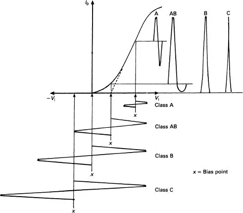
Class A
Class B
Class AB
Class C

Class D
Class E
Current dumping amplifiers
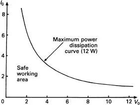
1.2 Distortions (see also under Measurements, p. 159)

Amplitude or non-linear distortion
Table of contents
- Cover
- Halftitle
- Dedication
- Title
- Copyright
- Contents
- Preface to the Second Edition
- Preface to the First Edition
- 1 Analogue systems and concepts
- 2 Antennas or aerials
- 3 Audio signal processing
- 4 Bar code and data matrix technology
- 5 Codes and coding formats
- 6 Computers in communications
- 7 Digital communication systems
- 8 Digital pulse code modulation
- 9 Electromagnetic compatibility/interference (EMC/EMI)
- 10 Encryption and decryption
- 11 Error control
- 12 Facsimile (Fax) systems
- 13 Filters
- 14 Frequency ranges in use
- 15 Image processing
- 16 Information theory
- 17 Logic
- 18 Measurement of system parameters
- 19 Memories
- 20 Microwave devices
- 21 Mixer signal processing
- 22 Modulation and demodulation
- 23 Networks
- 24 Noise
- 25 Optical communications, devices and systems
- 26 Power supplies
- 27 Propagation
- 28 Quality and reliability/quality assurance (QA)
- 29 Radar, navigation and tracking systems
- 30 Radio frequency receivers
- 31 Satellite systems
- 32 Semiconductor devices and technology
- 33 Signals
- 34 Spread spectrum techniques
- 35 Standards organisations and associated bodies
- 36 Telephony and associated systems
- 37 Television systems and signals
- 38 Transmission lines and waveguides
- 39 Video on demand systems
- 40 Videotex(t)
- 41 Wire-less distribution systems
- Appendix 1. CCITT recommendations
- Appendix 2. Abbreviations and acronyms
- Index
Frequently asked questions
- Essential is ideal for learners and professionals who enjoy exploring a wide range of subjects. Access the Essential Library with 800,000+ trusted titles and best-sellers across business, personal growth, and the humanities. Includes unlimited reading time and Standard Read Aloud voice.
- Complete: Perfect for advanced learners and researchers needing full, unrestricted access. Unlock 1.4M+ books across hundreds of subjects, including academic and specialized titles. The Complete Plan also includes advanced features like Premium Read Aloud and Research Assistant.
Please note we cannot support devices running on iOS 13 and Android 7 or earlier. Learn more about using the app