![]()
1 The PC
Ever since IBM entered the personal computer scene, it was clear that its ‘PC’ (first announced in 1981) would gain an immense following. In a specification that now seems totally inadequate, the original PC had an 8088 processor, 64–256 kilobyte (KB) of system board RAM (expandable to 640 KB with 384 KB fitted in expansion slots). It supported two 360 KB floppy disk drives, an 80 columns × 25 lines display, and 16 colours with an IBM colour graphics adapter.
The original PC was quickly followed by the PC-XT. This machine, an improved PC, with a single 5¼ in. 360 KB floppy disk drive and a 10 megabyte (MB) hard disk, was introduced in 1983. In 1984, the PC-XT was followed by a yet further enhanced machine, the PC-AT (where XT and AT stood for eXtended and Advanced Technology, respectively). The PC-AT used an 80286 microprocessor and catered for a 5¼ in. 1.2 MB floppy drive together with a 20 MB hard disk.
While IBM were blazing a trail, many other manufacturers were close behind. The standards set by IBM attracted much interest from other manufacturers, notable among whom were Compaq and Olivetti. These companies were not merely content to produce machines with an identical specification but went on to make further significant improvements. Other manufacturers were happy to simply ‘clone’ the PC; indeed, one could be excused for thinking that the highest accolade that could be offered by the computer press was that a machine was ‘IBM compatible’.
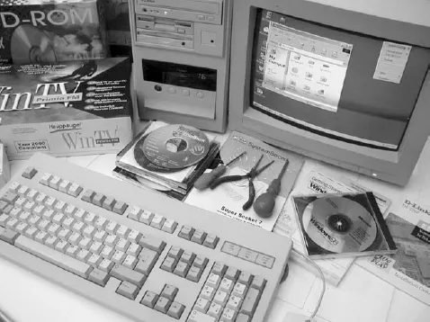
Photo 1.1 Setting up a PC requires access to both hardware and software
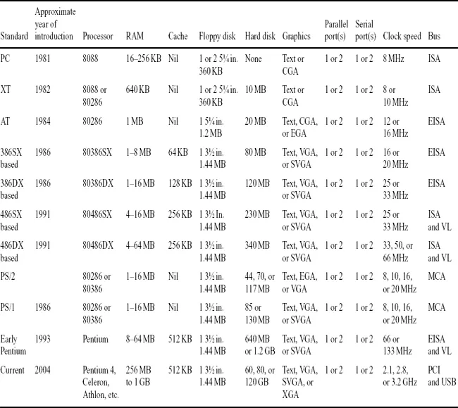
Table 1.1 Typical PC specifications from 1981 to the present day
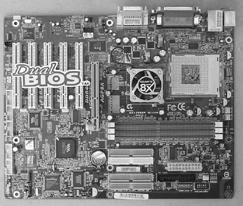
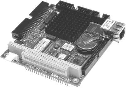
Photo 1.2 A modern high-specification dual-BIOS PC motherboard
This chapter sets out to introduce the PC and provide an insight into the architecture, construction, and operation of a ‘generic PC’. It should, perhaps, be stated that the term ‘PC’ now applies to such a wide range of equipment that it is difficult to pin down the essential ingredients of such a machine. However, at the risk of oversimplifying matters, a ‘PC’ need only satisfy two essential criteria:
Be based upon an Intel 16-, 32-, or 64-bit processor, such as a ’x86, Pentium, or a compatible device (such as a Celeron, Athlon, or Duron processor).
Be able to support the Microsoft MS-DOS operating system, Microsoft Windows, or a compatible operating system.
Other factors, such as available memory size, disk capacity, and display technology remain secondary.
To illustrate the progress in technology over the last 20 or so years, Table 1.1 shows typical specifications for various types of PC. However, before considering PC architecture in more detail, we shall begin by briefly describing the basic elements of a microcomputer system.
Microcomputer
systems
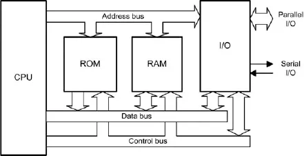
The principal elements within a microcomputer system consist of a central processing unit (CPU), read/write memory (RAM), read-only memory (ROM), together with one (or more) input/output (I/O) devices. These elements are connected together by a bus system along which data, address, and control signals are passed, as shown in Figure 1.1.
Figure 1.1 Elements of a microcomputer system
The CPU is the microprocessor itself (e.g. a x86 or Pentium device), whilst the read/write and read-only memory are implemented using a number of semiconductor memory devices (RAM and ROM, respectively).The semiconductor ROM provides non-volatile storage for part of the operating system code (the code remains intact when the power supply is disconnected, whereas the semiconductor RAM provides storage for the remainder of the operating system code, applications programs, and transient data. It is important to note that this memory is volatile, and any program or data stored within it will be lost when the power supply is disconnected.
The operating system is a collection of programs and software utilities that provide an environment in which applications software can easily interact with system hardware. The operating system also provides the user with a means of carrying out general housekeeping tasks, such as disk formatting, disk copying, etc. In order to provide a means of interaction with the user (via keyboard entered commands and onscreen prompts and messages), the operating system incorporates a shell program (e.g. the COMMAND.COM program provided within MSDOS).
Part of the semiconductor RAM is reserved for operating system use and for storage of a graphic/text display (as appropriate). In order to optimize the use of the available memory, most modern operating systems employ memory management techniques which allocate memory to transient programs and then release the memory when the program is terminated. A special type of program (known as a ‘terminate and stay resident’ program) can, however, remain resident in memory for immediate execution at some later stage (e.g. when another application program is running).
I/O devices provide a means of connecting external hardware, such as keyboards, displays, and disk controllers. I/O is usually handled by a number of specialized VLSI devices, each dedicated to a particular I/O function (such as disk control, graphics control, etc.). Such I/O devices are, in themselves, very complex and are generally programmable (requiring software configuration during system initialization).
Photo 1.3 Arcom's Pegasus embedded PC controller (photo courtesy of Arcom)
The elements within the microcomputer system shown in Figure 1.1 (CPU, ROM, RAM, and I/O) are connected together by three distinct bus systems:
1 The address bus along which address information is passed.
2 The data bus along which data is passed.
3 The control bus along which control signals are passed.
Data representation
The information present on the bus lines is digital and is represented by the two binary logic states: logic 1 (or high) and logic 0 (or low). All addresses and data values must therefore be coded in binary format with the most significant bit (MSB) present on the uppermost address or data line and the least significant bit (LSB) on the lowermost address or data line (labelled A0 and D0, respectively).
The bus lines (whether they be address, data, or control) are common to all four elements of the system. Data is passed via the data bus line in parallel groups of either 8, 16, 32, or 64 bits. An 8-bit group of data is commonly known as a byte whereas a 16-bit group is usually referred to as a word.
As an example, assume that the state of the eight data bus lines in a system at a particular instant of time is as shown in Figure 1.2.
The binary value (MSB first, LSB last) is 10100111 and its decimal value (found by adding together the decimal equivalents wherever a ‘1’ is present in the corresponding bit position) is 167.
It is often more convenient to express values in hexadecimal (base 16) format (see Appendix D). The value of the byte (found by grouping the binary digits into two 4-bit nibbles and then converting each to its corresponding hexadecimal character, is A7 (variously shown as...