The case studies provided in Case Studies for Advances in Paleoimagingwillprovide the reader with real-world scenarios and case examples that will help prepare researchers to discover new ways to apply the various modalities associated with the technology. This book is a follow-up to the Beckett and Conlogue's classic work Paleoimaging (2009) and companion to their new contribution Advances in Paleoimaging (2020). The case studies outlined demonstrate the problem-solving nature of imaging research and the application of critical thought to unique problems.
Further, Case Studies for Advances in Paleoimaging demonstrates the incredible depth of application of these modalities including photography, endoscopy, x-ray fluorescence, plane radiography, digital radiography, and advanced imaging modalities like multi-detector computed tomography, micro-computed tomography, and magnetic resonance imaging. Of particular note, case study seven, Contrast Media Injections, informs the researcher regarding methods to bring out specific anatomic structures that may be the target of a given research question.
Intended for students, faculty, and seasoned researchers, Case Studies for Advances in Paleoimagingpresents actual cases from the authors' vast experience in the application of paleoimaging modalities in order to answer unique research problems. The book also serves as a field manual for current and future researchers as they approach similar or new cases that present unique challenges. These cases demonstrate how the varied imaging methodologies can provide data which greatly enriches our understanding of the subject at hand, be it ancient cultural remains, forensic recovery, museum holdings, or other anthropological and archaeological artifacts.
Trusted by 375,005 students
Access to over 1.5 million titles for a fair monthly price.
Objective: Radiograph objects that are larger than the largest film holder or cassette available.
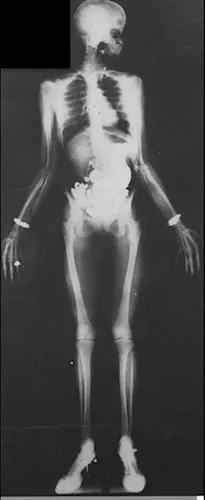
In 1934, Arthur W. Fuchs published an image of a full body in high heels in what looked like a pearl necklace (Figure 1.1). The image appeared in an article that he titled “Radiography of entire body employing one film and a single exposure” in the journal Radiography and Clinical Photography, which he edited for Kodak. There was great interest in capturing images of entire objects beyond the limitation of conventional size cassettes, that is, 14 × 17 inches (36 × 43 cm).
Figure 1.1. The image of a woman recorded on a single sheet of film that Arthur W. Fuchs published in 1934.
Due to beam divergence, multiple individual radiographs of a large object, changing the position of the X-ray source between exposures, will result in images that cannot be perfectly matched to create a single large image. This case study is comprised of multiple cases that span 40 years and demonstrate the evolution of imaging receptors in an attempt to repeat Fuchs’s work over eight decades ago.
After seeing the image, I really wanted to X-ray large objects, but the opportunity did not come until 1993 with a request from Andrew Nelson, a physical anthropology graduate student at UCLA, who wanted images of skeletons with acromegaly to be included in a study that he was conducting. Nelson identified two skeletons with the condition: one at the Mütter Museum, in the College of Physicians in Philadelphia, Pennyslvania, and the other in the anatomy department at the Yale School of Medicine in New Haven, Connecticut. Although both skeletons demonstrated the disease and were hanging in display cases, from an imaging prospective each had to be approached differently.
The skeletal remains of an individual at Yale were associated with Harvey Cushing, who first described the condition resulting from a tumor of the anterior pituitary gland, located at the base of the brain. The mass caused excess growth hormone to be secreted and resulted in the gigantic outward appearance of the individual. The skeleton was approximately 80 inches (203 cm) high and located in a corridor that would be unoccupied after 6 pm each evening. A 1940s vintage Picker Army Field unit, acquired from a veterinarian in eastern Connecticut, was donated to the diagnostic imaging program at Quinnipiac University to enable mobile radiography. Because it disassembled into five sections—a column with crank mechanism, X-ray tube with cables, the control unit, the transformer, and a base with wheels—it was considered a portable unit. The heaviest component, the transformer, weighted almost 100 pounds. However, because the X-ray tube could be rotated, it would be possible to direct a horizontal beam toward the skeleton.
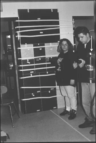
Although it was a functional X-ray source the unit presented several problems for the Yale study. The first obstacle was that the unit lacked a collimator light to indicate the distance required to cover the entire skeleton. The solution: back at the Quinnipiac diagnostic imaging laboratory, an assortment of various-sized cassettes were taped to the wall to achieve the 80-inch (203-cm) height required to expose the entire skeleton (Figure 1.2). Once it was determined that a 105-inch (267-cm) SID was the minimum distance required, the necessary exposure factors were established. A skeleton in the imaging lab was used with a nonscreen film holder to simulate the conditions at Yale. In order to reduce wear on the 50-year-old X-ray tube, a 50-inch (127-cm) SID was used to determine the optimal exposure factors: 48 kVp, 14 mA, and 14 separate 13 second exposures with a 30-second delay between exposures to permit the X-ray tube to cool. Using the inverse square law, it was calculated that 62 exposures were necessary at a 105-inch (267-cm) SID.
Figure 1.2. The assortment of various-sized cassettes taped to the wall in the Quinnipiac diagnostic imaging laboratory used to determine the minimum distance required to cover the 80-inch (203-cm) vertical height requirement. Two Quinnipiac diagnostic imaging students, Karen Garrick (Craft) and Jason Kreitner, worked on the study. Note the 1940s vintage Picker Army Field unit X-ray tube (arrow).
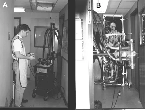
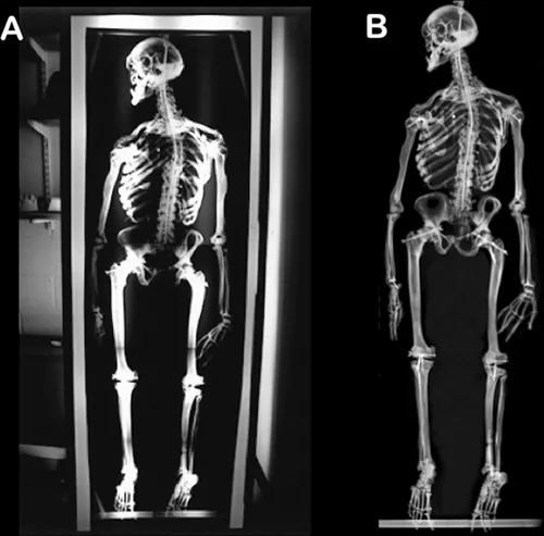
The next problem was the image receptor. Two sheets of foam core were fastened together to create a 25 × 80-inch (64 × 203-cm) rigid support. The foam core was taken into the university’s large photographic darkroom and laid on the floor, and 14 × 17-inch (36 × 43-cm) sheets of X-ray film were thumb-tacked to the rigid support. In order to ensure that there would be no gaps between films, care was taken to have at least an inch overlap of adjacent films. The loaded film holder was then wrapped with three layers of black gardening plastic with the ends folded over and sealed with duct tape. The mounted skeleton was removed from the display case, the anterior surface placed against the film holder, and a cloth strap was fastened across the back to secure it in place (Figure 1.3). Because of the 30-second delays between exposures, the total exposure time was approximately 45 minutes. Following the completion of the study, the film holder was brought back to the photographic darkroom at Quinnipiac and, unwrapped, the sheets of X-ray film were transferred into a light-tight film transport box, and finally were developed with the automatic processing unit in the X-ray lab. The processed films were trimmed to remove the regions of overlap and taped onto a specially constructed viewbox (Figure 1.4). In 2010, the X-ray films were digitized and stitched together to produce a single image.
Figure 1.3. (A) Jason Kreitner taking one of the exposures using the spring timer. (B) The horizontally directed X-ray tube directed toward the skeleton and nonscreen film holder covered in layers of gardening plastic (solid arrows). Note the cloth strap (dashed arrow) fastened across the back of the skeleton for stabilization.
Figure 1.4. (A) The trimmed radiographs were assembled and taped onto the opal plexiglass of the specially built viewbox. (B) In 2010, the original radiographs were scanned using a flatbed scanner with a transparency adapter. All of the images were stitched together to produce a single image.
The 7-foot 6-inch (229-cm) skeleton at the Mütter Museum has somewhat mysterious origins. Most of what is known is based on an article published by Guy Hinsdale in 1898. According to Hinsdale, the remains arrived at the museum in 1877 from Kentucky with the stipulation “no questions asked.” It was skeletonized and mounted for display and became known as the Kentucky or American Giant. The 1898 article discussed the connection between the pituitary gland and gigantism and a comparison to other skeletons in the collection.
The circumstances at the Mütter Museum presented a different set of problems. First, not only was the acromegalic skeleton was in a display case with two other skeletons, but it could not be removed from the exhibit [WS 1.5]. In addition, it was not possible to get more than a 94-inch (239-cm) SID, meaning that the X-ray could not cover an area larger than 40 inches (101 cm). Three 40 × 28-inch (101 × 71-cm) foam core–backed film holders were created as described in the previous Yale study [WS 1.6] and the skeleton was radiographed in three sections [WS 1.7]. The shorter SID reduced the necessary exposures to a total of 50 at 13 seconds each with a 30-second delay between successive exposures, or about 40 minutes total time. However, because there were three radiographs necessary to cover the entire skeleton, a total of two hours was required to complete the study. Instead of having to drive back to Connecticut to process the radiographs, all of the X-rays were developed at Graduate Hospital on South Street in Philadelphia, only a few miles from the museum. Unfortunately, the first set of radiographs was not acceptable due to blurred images. After much pondering, it was realized that during the nearly 40-minute exposure required for each section of the skeleton vibration was created by the air conditioning system periodically cycling on. It was necessary to reschedule another imaging session and coordinate the exposure times to avoid the vibrations. In addition to the AP set of radiographs, the final procedure included a lateral projection [WS 1.8].
Another opportunity to X-ray a large object came in August 2006 when the Slater Museum in Norwich, Connecticut, requested a radiographic examination of a statue of the Winged Victory of Samothrace. Complete details of the project are described in “Case Study 5: Manufactured or Created Objects.” However, the important considerations here were the long SID, 40 feet (12 m), the stature was on a pedestal approximately 15 feet (4.6 m) off the floor and the composition of plaster with iron rods employed for reinforcement. Therefore, higher kVp settings were necessary to penetrate the object and intensifying screens to reduce the exposure time were necessary. Three 14 × 17-inch (36 × 43-cm) cassettes were held together by creating a rigid foam core and cardboard backing to produce a single image receptor that covered a 42 × 17-inch (107 × 43-cm) area (Figure 1.5). In order to place the modified film holder against the wing, a scaffold needed to be erected and a cassette taped to the aluminum frame (Figure 1.6). The X-ray source was place on cart and positioned on the balcony facing each wing (Figure 1.7A). The 40-foot (12-m) SID required a total of 143 exposures at 90 kVp and 40 mAs over approximately a 90-minute period to complete one set of X-rays. Because the X-ray source was not equipped with a fan for cooling, an ice pack was taped to each side of the X-ray tube in order to facilitate cooling (Figure 1.7B). Following the exposures, the cassettes were unloaded and reloaded in a makeshift darkroom constructed in the back of a Dodge van (Figure 1.8). It required three sets of exposures, or about five and a half hours, to cover the entire right wing. All nine exposed films were transported 65 miles back to the X-ray lab at Quinnipiac for processing. Because of the thickness of the edges of the cassettes, the final images were not seamlessly matched (Figure 1.9). For the left wing, on the second visit to the museum, the repositioned X-ray source had a 20-foot (6.1-m) SID and required only 30 exposures at 90 kVp at 40 mAs. Once again, a total of three sets of images were necessary to demonstrate the internal structure of the...
Table of contents
Cover
Half-Title
Title
Copyright
Dedication
Contents
Preface
Acknowledgments
The Editors
Contributors
Case Study 1 Large Objects
Case Study 2 Zoological Specimens
Case Study 3 Skeletal Remains
Case Study 4 Mummified Remains
Case Study 5 Manufactured or Created Objects
Case Study 6 Teeth: Plane Radiography (Film); Clinical CT; MicroCT
Case Study 7 Contrast Media Injections
Case Study 8 Endoscopy and XRF Cases
Index
Frequently asked questions
Yes, you can cancel anytime from the Subscription tab in your account settings on the Perlego website. Your subscription will stay active until the end of your current billing period. Learn how to cancel your subscription
No, books cannot be downloaded as external files, such as PDFs, for use outside of Perlego. However, you can download books within the Perlego app for offline reading on mobile or tablet. Learn how to download books offline
Perlego offers two plans: Essential and Complete
Essential is ideal for learners and professionals who enjoy exploring a wide range of subjects. Access the Essential Library with 800,000+ trusted titles and best-sellers across business, personal growth, and the humanities. Includes unlimited reading time and Standard Read Aloud voice.
Complete: Perfect for advanced learners and researchers needing full, unrestricted access. Unlock 1.5M+ books across hundreds of subjects, including academic and specialized titles. The Complete Plan also includes advanced features like Premium Read Aloud and Research Assistant.
Both plans are available with monthly, semester, or annual billing cycles.
We are an online textbook subscription service, where you can get access to an entire online library for less than the price of a single book per month. With over 1.5 million books across 990+ topics, we’ve got you covered! Learn about our mission
Look out for the read-aloud symbol on your next book to see if you can listen to it. The read-aloud tool reads text aloud for you, highlighting the text as it is being read. You can pause it, speed it up and slow it down. Learn more about Read Aloud
Yes! You can use the Perlego app on both iOS and Android devices to read anytime, anywhere — even offline. Perfect for commutes or when you’re on the go. Please note we cannot support devices running on iOS 13 and Android 7 or earlier. Learn more about using the app
Yes, you can access Case Studies for Advances in Paleoimaging and Other Non-Clinical Applications by Ronald G. Beckett,Gerald J. Conlogue,Andrew Nelson in PDF and/or ePUB format, as well as other popular books in Ciencias sociales & Enseñanza de artes y humanidades. We have over 1.5 million books available in our catalogue for you to explore.