- 192 pages
- English
- ePUB (mobile friendly)
- Available on iOS & Android
eBook - ePub
Oscillator Circuits
About this book
This series of circuits provides designers with a quick source for oscillator circuits. Why waste time paging through huge encyclopedias when you can choose the topic you need and select any of the specialized circuits sorted by application?This book in the series has 250-300 practical, ready-to-use circuit designs, with schematics and brief explanations of circuit operation. The original source for each circuit is listed in an appendix, making it easy to obtain additional information.
- Ready-to-use circuits
- Grouped by application for easy look-up
- Circuit source listings
Tools to learn more effectively

Saving Books

Keyword Search

Annotating Text

Listen to it instead
Information
1
Audio Oscillators
The sources of the following circuits are contained in the Sources section, which begins on page 173. The figure number contained in the box of each circuit correlates to the source entry in the Sources section.
Wen-Bridge Sine-Wave Oscillator
Phase-Shift Oscillator
Wien-Bridge Oscillator
Code-Practice Oscillator
Tone Encoder
Feedback Oscillator
Wien-Bridge Oscillator
Wen-Bridge Oscillator
Phase-Shift Oscillator
800-Hz Oscillator
Wien-Bridge Oscillator
Wien-Bridge Sine-Wave Oscillator
Sine-Wave Oscillator
Easily Tuned Sine-/Square-Wave Oscillator
Very-Low-Frequency Generator
Audio Oscillator
Electronic Bagpipe
Simple Audio Sine-Wave Generator
Low-Cost Wien-Bridge Oscillator
Modified UJT Relaxation Oscillator
A 555 RC Audio Oscillator
Wien-Bridge Oscillator Uses CMOS Chip
Adjustable Sine-Wave Audio Oscillator
One-IC Audio Generator
Simple Two-Tone Generator
Low-Distortion Thermally Stabilized Wien-Bridge Oscillator
Audio Oscillator
Audio Generator
Single-Supply Wien-Bridge Oscillator
Super-Low-Distortion Variable Sine-Wave Oscillator
1-kHz Oscillator
Inexpensive Oscillator is Temperature Stable
Code-Practice Oscillator
Audio Oscillator
WIEN-BRIDGE SINE-WAVE OSCILLATOR
The 2N5457 JFET, as a voltage variable resistor in the amplifier feedback loop, produces a low distortion, constant amplitude sine wave getting the amplifier loop gain just right. The LM103 zener diode provides the voltage reference for the peak sine wave amplitude.
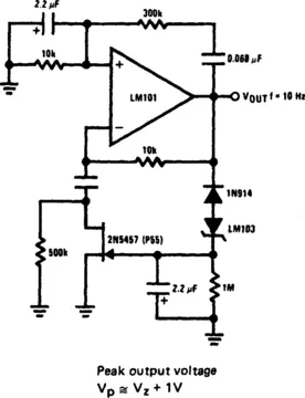
Fig. 1-1 NATIONAL SEMICONDUCTOR
PHASE-SHIFT OSCILLATOR
Circuit uses a simple RC network to produce an exceptionally shrill tone from a miniature speaker. With the parts values shown, the circuit oscillates at a frequency of 3.6 kHz and drives a miniature 2½Π speaker at ear-piercing volume. The output waveform is a square wave with a width of 150 µs, sloping rise and fall times, and a peak-to-peak amplitude of 4.2 volts (when powered by 9 volts). Current drain of the oscillator is 90 mA at 9 volts, and total power dissipation at this voltage is 0.81 watt, which is well below the 1.25 watts the 14-pin version will absorb (at room temperature) before shutting down.
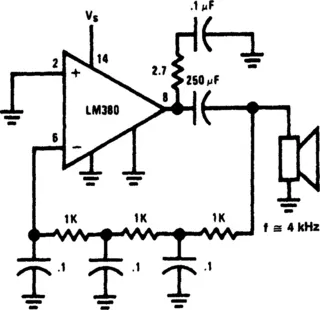
Fig. 1-2 NATIONAL SEMICONDUCTOR
WIEN-BRIDGE OSCILLATOR
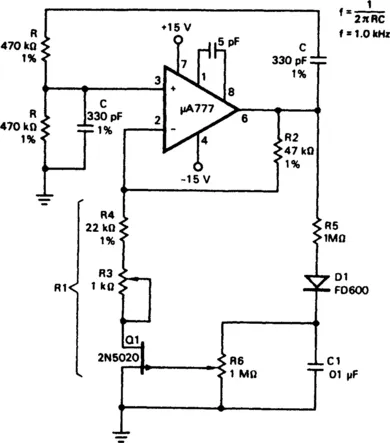
Fig. 1-3 FAIRCHILD CAMERA
Field effect transistor, Q1, operates in the linear resistive region to provide automatic gain control. Because the attenuation of the RC network is one-third at the zero phase-shift oscillation frequency, the amplifier gain determined by resistor R2 and equivalent resistor R1 must be just equal to three to make up the unity-gain positive-feedback requirement needed for stable oscillation. Resistors R3 and R4 are set to approximately 1000 ohms less than the required R1 resistance. The FET dynamically provides the trimming resistance needed to make R1 one-half of the resistance of R2. The...
Table of contents
- Cover image
- Title page
- Table of Contents
- Copyright
- Other Books in this Series
- Introduction
- Chapter 1: Audio Oscillators
- Chapter 2: Crystal Oscillators
- Chapter 3: Function Generators
- Chapter 4: Miscellaneous Oscillators
- Chapter 5: Multivibrators and Square-Wave Oscillators
- Chapter 6: RF Oscillators
- Chapter 7: Sirens, Warblers and Wailers
- Chapter 8: Voltage-Controlled Oscillators
- Sources
- Index
Frequently asked questions
Yes, you can cancel anytime from the Subscription tab in your account settings on the Perlego website. Your subscription will stay active until the end of your current billing period. Learn how to cancel your subscription
No, books cannot be downloaded as external files, such as PDFs, for use outside of Perlego. However, you can download books within the Perlego app for offline reading on mobile or tablet. Learn how to download books offline
Perlego offers two plans: Essential and Complete
- Essential is ideal for learners and professionals who enjoy exploring a wide range of subjects. Access the Essential Library with 800,000+ trusted titles and best-sellers across business, personal growth, and the humanities. Includes unlimited reading time and Standard Read Aloud voice.
- Complete: Perfect for advanced learners and researchers needing full, unrestricted access. Unlock 1.4M+ books across hundreds of subjects, including academic and specialized titles. The Complete Plan also includes advanced features like Premium Read Aloud and Research Assistant.
We are an online textbook subscription service, where you can get access to an entire online library for less than the price of a single book per month. With over 1 million books across 990+ topics, we’ve got you covered! Learn about our mission
Look out for the read-aloud symbol on your next book to see if you can listen to it. The read-aloud tool reads text aloud for you, highlighting the text as it is being read. You can pause it, speed it up and slow it down. Learn more about Read Aloud
Yes! You can use the Perlego app on both iOS and Android devices to read anytime, anywhere — even offline. Perfect for commutes or when you’re on the go.
Please note we cannot support devices running on iOS 13 and Android 7 or earlier. Learn more about using the app
Please note we cannot support devices running on iOS 13 and Android 7 or earlier. Learn more about using the app
Yes, you can access Oscillator Circuits by Rudolf F. Graf in PDF and/or ePUB format, as well as other popular books in Design & Industrial Design. We have over one million books available in our catalogue for you to explore.